Proj-2014-2015-Mini datacenter Systeme SRS: Difference between revisions
Jake.morison (talk | contribs) |
Jake.morison (talk | contribs) |
||
| (7 intermediate revisions by the same user not shown) | |||
| Line 3: | Line 3: | ||
=1. Introduction= |
=1. Introduction= |
||
==1.1 Purpose of the requirements document== |
==1.1 Purpose of the requirements document== |
||
This Software Requirements Specification (SRS) identifies the requirements for this datacenter |
This Software Requirements Specification (SRS) identifies the requirements for this datacenter. The purpose of this document is to easily explain the development of this project and to provide instructions to understand and use the datacenter. |
||
==1.2 Scope of the product== |
==1.2 Scope of the product== |
||
The purpose of this project is to provide an userfriendly web interface to simulate and use a small datacenter. |
|||
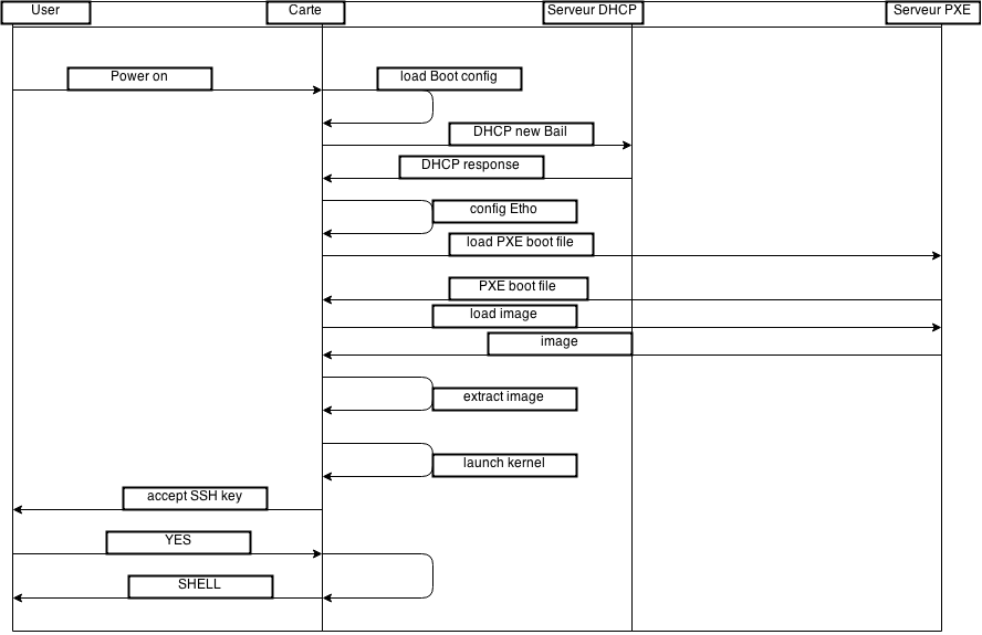
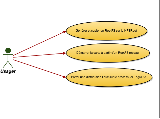
The purpose of this project is to provide a mechanism and scripts to orchestrate the boot of the Jetson TK1 card from image OS store on an NFS Server in the datacenter. |
|||
Each node of the datacenter can perform some operations, users can interact with a group of nodes or a specific one. |
|||
==1.3 Definitions, acronyms and abbreviations== |
==1.3 Definitions, acronyms and abbreviations== |
||
* node |
* node |
||
| Line 26: | Line 28: | ||
=2. General description= |
=2. General description= |
||
==2.1 Product perspective== |
==2.1 Product perspective== |
||
Tout d'abord, notre projet se base sur une infrastructure simulée par OAR-docker. Cette infractructure contient divers noeuds, chacun exploitable par un un utilisateur à la fois. |
|||
Notre but est de produire une interface web facilement utilisable et compréhensible par des non-initiés, |
|||
==2.2 Product functions== |
==2.2 Product functions== |
||
Cette interface leur permettra de contrôler les noeuds qu'ils désirent. Ces noeuds sont capables d'exécuter diverses opérations. |
|||
UML Class Diagram |
UML Class Diagram |
||
[[File:class.png]] |
[[File:class.png]] |
||
UML Activity Diagram |
UML Activity Diagram |
||
Latest revision as of 11:56, 9 March 2015
1. Introduction
1.1 Purpose of the requirements document
This Software Requirements Specification (SRS) identifies the requirements for this datacenter. The purpose of this document is to easily explain the development of this project and to provide instructions to understand and use the datacenter.
1.2 Scope of the product
The purpose of this project is to provide a mechanism and scripts to orchestrate the boot of the Jetson TK1 card from image OS store on an NFS Server in the datacenter.
1.3 Definitions, acronyms and abbreviations
- node
- datacenter
- frontend
- oar
- docker
1.4 References
- Get Started Jetson TK1
- Grid'5000
- OAR OAR is a versatile resource and task manager (also called a batch scheduler) for HPC clusters and other computing infrastructures. It's used on Grid'5000.
- oar-docker: oar-docker is a set of docker images especially configured for deploying your own OAR cluster. The main idea is to have a mini development cluster with a frontend, a server and some nodes that launch in just a few seconds on a simple laptop.
- Kameleon : Kameleon is a simple but powerful tool to generate customized appliances.
1.5 Overview of the remainder of the document
The SRS document includes 3 main chapters :
- General description, which contains the general characteristics of the project and our implementation choices.
- Specific requirements, which gives the main requirements of each function.
- Product evolution, which details the differents steps of implementation we chose.
2. General description
2.1 Product perspective
2.2 Product functions
2.3 User characteristics
L'utilisateur n'a pas besoin de connaître la façon dont s'instancie une ressource pour pouvoir utiliser l'interface.
2.4 General constraints
accès à la simulation dnas un environnement privé OAR-docker installé
2.5 Assumptions and dependencies
Chaque utilisateur ne travaille pas sur une même infrastructure, puisque les environnements sont privés.
3.Specific requirements, covering functional, non-functional and interface requirements
- document external interfaces,
- describe system functionality and performance
- specify logical database requirements,
- design constraints,
- emergent system properties and quality characteristics.
3.1 Requirement X.Y.Z (in Structured Natural Language)
Function:
Description:
Inputs:
Source:
Outputs:
Destination:
Action:
- Natural language sentences (with MUST, MAY, SHALL)
- Graphical Notations : UML Sequence w/o collaboration diagrams, Process maps, Task Analysis (HTA, CTT)
- Mathematical Notations
- Tabular notations for several (condition --> action) tuples
Non functional requirements:
Pre-condition:
Post-condition:
Side-effects:
4. Product evolution
5. Appendices
This document is inspired of the IEEE/ANSI 830-1998 Standard.
References:
- http://www.cs.st-andrews.ac.uk/~ifs/Books/SE9/Presentations/PPTX/Ch4.pptx
- http://en.wikipedia.org/wiki/Software_requirements_specification
- IEEE Recommended Practice for Software Requirements Specifications IEEE Std 830-1998


