Proj-2013-2014-RobAIR-2/How to create robAIR: Difference between revisions
No edit summary |
No edit summary |
||
| (21 intermediate revisions by the same user not shown) | |||
| Line 5: | Line 5: | ||
Our robot will use a propulsion system 24V type robot Devantech RD02 presented below: |
Our robot will use a propulsion system 24V type robot Devantech RD02 presented below: |
||
[[ |
[[Image:Devantech-rd03-24v-robot-drive-system-a.jpg|400px|thumb|center|Devantech RD02]] |
||
We 'll climb the two wheels on the underside of the base of our robot with the screws that were provided . For stability, we will add multidirectional wheels at the front and rear so that the robot can move properly. Here is a photo montage : |
We 'll climb the two wheels on the underside of the base of our robot with the screws that were provided . For stability, we will add multidirectional wheels at the front and rear so that the robot can move properly. Here is a photo montage : |
||
[[ |
[[Image:Roues_robot.png|400px|thumb|center|Mounting of wheels]] |
||
Driver Robot System 24 V RD03 Devantech RD03 is a powerful robot control system , consisting of a DC Motor Controller MD49 - 24V 5A Devantech , two 24V Gear Motor with encoder , two mounting brackets, two 125 mm wheels with hubs already set. Screws to attach the motors to the brackets and a hex wrench to screw the hub are included. Only a 24V battery is needed to power the system. The MD49 is controlled with a series of logic level port, as well selectable 9600 to 38,400 baud. The MD49 has two modes of operation, direct individual motor control or the ability to send commands to speed and steering . |
Driver Robot System 24 V RD03 Devantech RD03 is a powerful robot control system , consisting of a DC Motor Controller MD49 - 24V 5A Devantech , two 24V Gear Motor with encoder , two mounting brackets, two 125 mm wheels with hubs already set. Screws to attach the motors to the brackets and a hex wrench to screw the hub are included. Only a 24V battery is needed to power the system. The MD49 is controlled with a series of logic level port, as well selectable 9600 to 38,400 baud. The MD49 has two modes of operation, direct individual motor control or the ability to send commands to speed and steering . |
||
| Line 17: | Line 17: | ||
The batteries we have chosen to use are 12V batteries from Yuasa brand: |
The batteries we have chosen to use are 12V batteries from Yuasa brand: |
||
[[ |
[[Image:Yuasa-batteries.jpg|400px|thumb|center|Battery used in our robot]] |
||
We subsequently positioning the battery stands on the base of the robot and the battery placed in the following manner : |
We subsequently positioning the battery stands on the base of the robot and the battery placed in the following manner : |
||
[[ |
[[Image:Batteries.png|400px|thumb|center|Mounting of batteries]] |
||
We will then connect in series via connectors and directly on the engine controller as follows : |
We will then connect in series via connectors and directly on the engine controller as follows : |
||
[[ |
[[Image:Branchement_carte_moteur.png|400px|thumb|center|Connection the engine board]] |
||
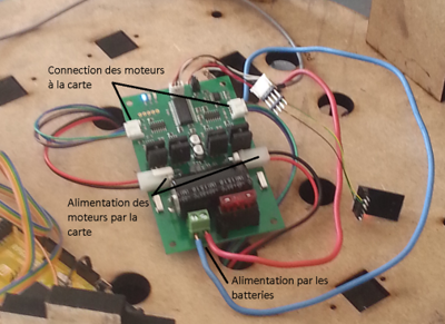
The wheels are then powered by the battery via map . In addition, the motors are connected directly to the card , which will link information to the tablet via the connector that we can see on the right. |
The wheels are then powered by the battery via map . In addition, the motors are connected directly to the card , which will link information to the tablet via the connector that we can see on the right. |
||
| Line 34: | Line 34: | ||
The infrared sensors are Arduino switch adjustable infrared sensor to detect 3 -80cm Type : |
The infrared sensors are Arduino switch adjustable infrared sensor to detect 3 -80cm Type : |
||
[[ |
[[Image:Ultrasound.jpg|300px|thumb|center|Infrared sensor]] |
||
The switch of the infrared sensor is an adjustable set of the transmitter and receiver to a photoelectric switch of sensors . The detection distance can be adjusted depending on the application . The sensor has a detection range from 3cm -80cm . The output switching signal is different depending on obstacles . It remains high when no obstacle is low when there are obstacles. |
The switch of the infrared sensor is an adjustable set of the transmitter and receiver to a photoelectric switch of sensors . The detection distance can be adjusted depending on the application . The sensor has a detection range from 3cm -80cm . The output switching signal is different depending on obstacles . It remains high when no obstacle is low when there are obstacles. |
||
We will fix the structure through the rings provided with sensors: |
We will fix the structure through the rings provided with sensors: |
||
[[ |
[[Image:Infrarouge_wiki.png|600px|thumb|center|Mounting the infrared sensors]] |
||
== Ultrasonic sensors == |
== Ultrasonic sensors == |
||
| Line 45: | Line 45: | ||
Our robot will use ultrasonic sensor HC- SR04 we can see below : |
Our robot will use ultrasonic sensor HC- SR04 we can see below : |
||
[[ |
[[Image:Capteur-ultrason-hc-sr04.jpg|300px|thumb|center|Ultrasound sensor]] |
||
This module simply has 4 output pins : VCC, trig , ECHO, GND . It is very easy to interface to a microcontroller . The entire process is as follows : |
This module simply has 4 output pins : VCC, trig , ECHO, GND . It is very easy to interface to a microcontroller . The entire process is as follows : |
||
| Line 54: | Line 54: | ||
We have established the structure as follows : |
We have established the structure as follows : |
||
[[ |
[[Image:Capteur-ultrason.png|400px|thumb|center|Mounting the ultrasound sensors]] |
||
= Installing the Kinect = |
= Installing the Kinect = |
||
In our implementation , we did not use the Kinect camera, but as it will be used in subsequent iterations , we decided to place it. Given that the Kinect camera will enable remoting . We must place it on top of the robot, so it is an overall view of the room, just above the tablet support : |
In our implementation , we did not use the Kinect camera, but as it will be used in subsequent iterations , we decided to place it. Given that the Kinect camera will enable remoting . We must place it on top of the robot, so it is an overall view of the room, just above the tablet support : |
||
[[Image:Photo_robot.jpg|400px|thumb|center|Robot overview]] |
|||
It will be directly connected to the tablet via USB hub. |
It will be directly connected to the tablet via USB hub. |
||
| Line 65: | Line 66: | ||
During the movement of the robot, we dynamically construct a map showing the room. The final result will look like this : |
During the movement of the robot, we dynamically construct a map showing the room. The final result will look like this : |
||
[[Image:Map.jpg|400px|thumb|center|Final rending of the map]] |
|||
To do this, we need to place the Lidar on top of the substrate as follows : |
|||
[[Image:Lidar.png|400px|thumb|center|Placing the lidar]] |
|||
| ⚫ | Lidar we used is sensor type Distance Scanning Laser URG- 04LX - UG01 Hokuyo. The Scanning Laser Rangefinder URG- 04LX - UG01 Rangefinder is a small , affordable and accurate laser scanner which is perfect for robotic applications. The URG- 04LX - UG01 is capable of indicating the distance of 20 mm to 5600 mm ( 1 mm resolution ) in an arc of 240 ° ( angular resolution 0.36 °) . It will be connected directly to the tablet via USB hub. |
||
| ⚫ | |||
| ⚫ | Lidar we used is sensor type Distance Scanning Laser URG- 04LX - UG01 Hokuyo. |
||
| ⚫ | |||
Connection of sensors on the Arduino board is a very important step in the assembly of our robot, bad connections on the pins may cause a malfunction of the robot. Here is a precise ultrasound sensor diagram : |
Connection of sensors on the Arduino board is a very important step in the assembly of our robot, bad connections on the pins may cause a malfunction of the robot. Here is a precise ultrasound sensor diagram : |
||
[[Image:Ultrason.png|400px|thumb|center|Connecting the ultrasound]] |
|||
Thus we see that to connect the sensors to the Arduino board , we need to connect the VCC pin to power the Arduino board , the pin corresponding to the emission of ultrasound or the TRIG pin to output , corresponding to the spindle receiving the ECHO signal to an input pin , and finally to the ground pin GND of the Arduino . |
Thus we see that to connect the sensors to the Arduino board , we need to connect the VCC pin to power the Arduino board , the pin corresponding to the emission of ultrasound or the TRIG pin to output , corresponding to the spindle receiving the ECHO signal to an input pin , and finally to the ground pin GND of the Arduino . |
||
| Line 76: | Line 84: | ||
Digital sensors also have 3 son connection : a 5V supply (usually red wire) , ground wire (green wire) and the output value (yellow wire). |
Digital sensors also have 3 son connection : a 5V supply (usually red wire) , ground wire (green wire) and the output value (yellow wire). |
||
[[Image:Infrarouge.png|400px|thumb|center|Connecting the infrared]] |
|||
Three son are connected as follows : |
Three son are connected as follows : |
||
| Line 86: | Line 94: | ||
Here's a final photo of the connection of sensors: |
Here's a final photo of the connection of sensors: |
||
[[Image:Branchement_shield.jpg|400px|thumb|center|Connecting sensors to the shield]] |
|||
Latest revision as of 12:05, 8 April 2014
We will present all the steps of mounting the robot. The model of the structure was created by Didier Donsez , professor at the University Grenoble 1 and in particular Polytech'Grenoble .
Mounting wheels
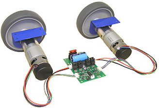
Our robot will use a propulsion system 24V type robot Devantech RD02 presented below:
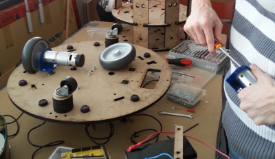
We 'll climb the two wheels on the underside of the base of our robot with the screws that were provided . For stability, we will add multidirectional wheels at the front and rear so that the robot can move properly. Here is a photo montage :
Driver Robot System 24 V RD03 Devantech RD03 is a powerful robot control system , consisting of a DC Motor Controller MD49 - 24V 5A Devantech , two 24V Gear Motor with encoder , two mounting brackets, two 125 mm wheels with hubs already set. Screws to attach the motors to the brackets and a hex wrench to screw the hub are included. Only a 24V battery is needed to power the system. The MD49 is controlled with a series of logic level port, as well selectable 9600 to 38,400 baud. The MD49 has two modes of operation, direct individual motor control or the ability to send commands to speed and steering .
Installation of batteries
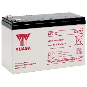
The batteries we have chosen to use are 12V batteries from Yuasa brand:
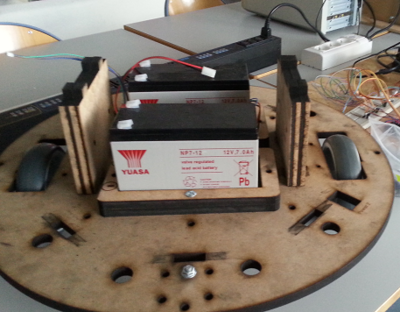
We subsequently positioning the battery stands on the base of the robot and the battery placed in the following manner :
We will then connect in series via connectors and directly on the engine controller as follows :
The wheels are then powered by the battery via map . In addition, the motors are connected directly to the card , which will link information to the tablet via the connector that we can see on the right.
Determination of sensors
To continue with the installation of our robot , we will fix all the sensors that will be used later on our structure. We have two different types of sensors : infrared sensors on the basis of the structure , and the ultrasound sensors fixed on the sides of the structure .
Infrared sensors
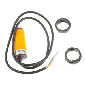
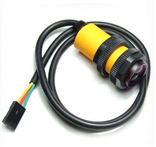
The infrared sensors are Arduino switch adjustable infrared sensor to detect 3 -80cm Type :
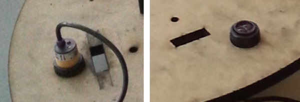
The switch of the infrared sensor is an adjustable set of the transmitter and receiver to a photoelectric switch of sensors . The detection distance can be adjusted depending on the application . The sensor has a detection range from 3cm -80cm . The output switching signal is different depending on obstacles . It remains high when no obstacle is low when there are obstacles. We will fix the structure through the rings provided with sensors:
Ultrasonic sensors
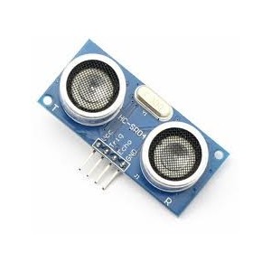
Our robot will use ultrasonic sensor HC- SR04 we can see below :
This module simply has 4 output pins : VCC, trig , ECHO, GND . It is very easy to interface to a microcontroller . The entire process is as follows :
- Put the pin " TRIG " a high level pulse (5V ) for at least 10us and the module starts reading
- At the end of the extent, if detects an object in front of him , the pin " ECHO" goes high (5V) " PulseIn ()" .
- The remote location of the obstacle is proportional to the duration of this pulse . It is very easy to calculate this distance.
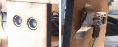
We have established the structure as follows :
Installing the Kinect
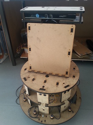
In our implementation , we did not use the Kinect camera, but as it will be used in subsequent iterations , we decided to place it. Given that the Kinect camera will enable remoting . We must place it on top of the robot, so it is an overall view of the room, just above the tablet support :
It will be directly connected to the tablet via USB hub.
Positioning Lidar
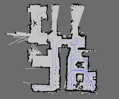
During the movement of the robot, we dynamically construct a map showing the room. The final result will look like this :
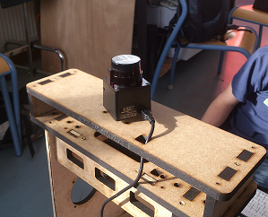
To do this, we need to place the Lidar on top of the substrate as follows :
Lidar we used is sensor type Distance Scanning Laser URG- 04LX - UG01 Hokuyo. The Scanning Laser Rangefinder URG- 04LX - UG01 Rangefinder is a small , affordable and accurate laser scanner which is perfect for robotic applications. The URG- 04LX - UG01 is capable of indicating the distance of 20 mm to 5600 mm ( 1 mm resolution ) in an arc of 240 ° ( angular resolution 0.36 °) . It will be connected directly to the tablet via USB hub.
Connecting sensors to the Arduino board
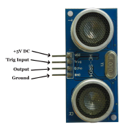
Connection of sensors on the Arduino board is a very important step in the assembly of our robot, bad connections on the pins may cause a malfunction of the robot. Here is a precise ultrasound sensor diagram :
Thus we see that to connect the sensors to the Arduino board , we need to connect the VCC pin to power the Arduino board , the pin corresponding to the emission of ultrasound or the TRIG pin to output , corresponding to the spindle receiving the ECHO signal to an input pin , and finally to the ground pin GND of the Arduino . We will have to ensure noted pines on which the TRIG and ECHO are connected, because we will need to configure the Arduino sketch based . Digital sensors also have 3 son connection : a 5V supply (usually red wire) , ground wire (green wire) and the output value (yellow wire).
Three son are connected as follows : - Red wire sensor 5V : 5V (power) Arduino (+ on the shield ) - Green wire sensor GND : GND (ground) Arduino ( - on the shield ) - Yellow wire sensor output : DIGITAL INPUT (DIGITAL) Arduino (S on the shield )
Please note once again the digital inputs used as the Arduino sketch strongly depends .
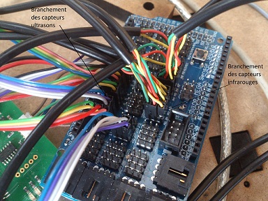
Here's a final photo of the connection of sensors:
