Ardumoto - Motor Driver Shield: Difference between revisions
Jump to navigation
Jump to search
No edit summary |
|||
| Line 2: | Line 2: | ||
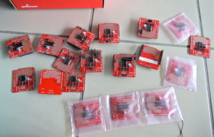
[[Image:Ardumoto - Motor Driver Shield.jpg|300px|thumb|right|Ardumoto - Motor Driver Shield]] |
[[Image:Ardumoto - Motor Driver Shield.jpg|300px|thumb|right|Ardumoto - Motor Driver Shield]] |
||
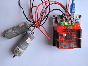
[[Image:Ardumoto+STM32Nucleo.jpg|300px|thumb|right|Ardumoto - Motor Driver Shield on a STM32 Nucleo F401]] |
[[Image:Ardumoto+STM32Nucleo.jpg|300px|thumb|right|Ardumoto - Motor Driver Shield on a STM32 Nucleo F401]] |
||
Shield Arduino utilisant un pont H L298 pour piloter 2 voies jusqu'à 2 ampères. |
|||
Voir http://www.sparkfun.com/products/9815 |
Voir http://www.sparkfun.com/products/9815 |
||
| ⚫ | |||
| ⚫ | |||
| ⚫ | |||
| ⚫ | |||
| ⚫ | |||
| ⚫ | |||
<pre> |
<pre> |
||
/* |
/* |
||
| Line 143: | Line 151: | ||
</pre> |
</pre> |
||
| ⚫ | |||
| ⚫ | |||
| ⚫ | |||
| ⚫ | |||
Revision as of 16:01, 8 November 2014
Shield Arduino utilisant un pont H L298 pour piloter 2 voies jusqu'à 2 ampères.
Voir http://www.sparkfun.com/products/9815
STM32 Nucleo
Voir
- http://developer.mbed.org/components/SparkFun-Ardumoto-Shield/
- http://developer.mbed.org/users/donsez/code/ArduMotoShield/
Arduino
/*
 5/22/2012
  Timothy Holmberg
  SparkFun Electronics

  This code includes the ddition of fade in and out PWM. Also a stop feature. And the addition of individual functions for motor control

  This was a revision of the example sketch that originated from Pete Dokter's code for Arduino that shows very basically how to control an Ardumoto
  motor driver shield with a 5V Arduino controller board. http://www.sparkfun.com/datasheets/DevTools/Arduino/Ardumoto_test_3.pde

  This also includes parts of the Fading Example,  Created 1 Nov 2008 By David A. Mellis, modified 30 Aug 2011 By Tom Igoe http://arduino.cc/en/Tutorial/Fading

*/

int pwm_a = 3;   //PWM control for motor outputs 1 and 2 is on digital pin 3
int pwm_b = 11;  //PWM control for motor outputs 3 and 4 is on digital pin 11
int dir_a = 12;  //direction control for motor outputs 1 and 2 is on digital pin 12
int dir_b = 13;  //direction control for motor outputs 3 and 4 is on digital pin 13
int val = 0;     //value for fade

void setup()
{
  pinMode(pwm_a, OUTPUT);  //Set control pins to be outputs
  pinMode(pwm_b, OUTPUT);
  pinMode(dir_a, OUTPUT);
  pinMode(dir_b, OUTPUT);

  analogWrite(pwm_a, 100);  //set both motors to run at (100/255 = 39)% duty cycle (slow)
  analogWrite(pwm_b, 100);

}

void loop()
{
  forw();         //Set Motors to go forward Note : No pwm is defined with the for function, so that fade in and out works
  fadein();       //fade in from 0-255
  delay(1000);
  forward();      //continue full speed forward
  delay(1000);
  fadeout();      //Fade out from 255-0
  delay(1000);    //Wait one second

  stopped();      // stop for 2 seconds
  delay(2000);


  back();         //Set motors to revers. Note : No pwm is defined with the back function, so that fade in and out works
  fadein();       //fade in from 0-255
  delay(1000);
  backward();     //full speed backward
  delay(1000);
  fadeout();      //Fade out from 255-0
  delay(1000);
}


/* Let's take a moment to talk about these functions. The forw and back functions are simply designating the direction the motors will turn once they are fed a PWM signal.
If you only call the forw, or back functions, you will not see the motors turn. On a similar note the fade in and out functions will only change PWM, so you need to consider
the direction you were last set to. In the code above, you might have noticed that I called forw and fade in the same grouping. You will want to call a new direction, and then
declare your pwm fade. There is also a stop function.
*/

void forw() // no pwm defined
{
  digitalWrite(dir_a, HIGH);  //Reverse motor direction, 1 high, 2 low
  digitalWrite(dir_b, HIGH);  //Reverse motor direction, 3 low, 4 high
}

void back() // no pwm defined
{
  digitalWrite(dir_a, LOW);  //Set motor direction, 1 low, 2 high
  digitalWrite(dir_b, LOW);  //Set motor direction, 3 high, 4 low
}

void forward() //full speed forward
{
  digitalWrite(dir_a, HIGH);  //Reverse motor direction, 1 high, 2 low
  digitalWrite(dir_b, HIGH);  //Reverse motor direction, 3 low, 4 high
  analogWrite(pwm_a, 255);    //set both motors to run at (100/255 = 39)% duty cycle
  analogWrite(pwm_b, 255);
}

void backward() //full speed backward
{
  digitalWrite(dir_a, LOW);  //Set motor direction, 1 low, 2 high
  digitalWrite(dir_b, LOW);  //Set motor direction, 3 high, 4 low
  analogWrite(pwm_a, 255);   //set both motors to run at 100% duty cycle (fast)
  analogWrite(pwm_b, 255);
}

void stopped() //stop
{
  digitalWrite(dir_a, LOW); //Set motor direction, 1 low, 2 high
  digitalWrite(dir_b, LOW); //Set motor direction, 3 high, 4 low
  analogWrite(pwm_a, 0);    //set both motors to run at 100% duty cycle (fast)
  analogWrite(pwm_b, 0);
}

void fadein()
{
  // fade in from min to max in increments of 5 points:
  for(int fadeValue = 0 ; fadeValue <= 255; fadeValue +=5)
  {
     // sets the value (range from 0 to 255):
    analogWrite(pwm_a, fadeValue);
    analogWrite(pwm_b, fadeValue);
    // wait for 30 milliseconds to see the dimming effect
    delay(30);
  }
}

void fadeout()
{
  // fade out from max to min in increments of 5 points:
  for(int fadeValue = 255 ; fadeValue >= 0; fadeValue -=5)
  {
    // sets the value (range from 0 to 255):
    analogWrite(pwm_a, fadeValue);
    analogWrite(pwm_b, fadeValue);
    // wait for 30 milliseconds to see the dimming effect
    delay(30);
}
}

void astop()                   //stop motor A
{
  analogWrite(pwm_a, 0);    //set both motors to run at 100% duty cycle (fast)
}

void bstop()                   //stop motor B
{
  analogWrite(pwm_b, 0);    //set both motors to run at 100% duty cycle (fast)
}

