Proj-2012-2013-BuildingManagementSystem/SRS: Difference between revisions
(Created page with "The document provides a template of the Software Requirements Specification (SRS). It is inspired of the IEEE/ANSI 830-1998 Standard. {|class="wikitable alternance" |+ Docume…") |
No edit summary |
||
| Line 1: | Line 1: | ||
The document provides a template of the Software Requirements Specification (SRS). It is inspired of the IEEE/ANSI 830-1998 Standard. |
|||
Latest revision as of 08:08, 11 April 2013
| Version | Date | Authors | Description | Validator | Validation Date | |
|---|---|---|---|---|---|---|
| 0.1.0 | 2013/01/21 | Mame Daba Diouf | TBC | TBC | TBC |
1. Introduction
1.1 Purpose of the requirements document
This document includes the descriptions of the software services and constraints that should be respected during its development.
It is intended to client engineers and managers, software developers, software users and contractors so that it allows them to understand and validate what the software will do.
1.2 Scope of the product
The name of the product is BMS.
BMS:
- Will control temperature, ventilation, lighting in a building, report residents’ preferences
- Will NOT include security monitor.
1.3 Definitions, acronyms and abbreviations
- BMS = Building Mangaement System
- HVAC = Heating Ventilation Air Conditionning
1.4 References
IEEE Recommended Practice for Software Requirements Specifications IEEE Std 830-1998
1.5 Overview of the remainder of the document
The rest of the document contains, along these lines :
- The overall descriptions
- The specific requirements and
- Supporting information
2. General description
2.1 Product perspective
2.2 Product functions
The major functions that the BMS will perform are :
- HVAC software programs
- Panel with LCD display
- Weekly time program (optional)
- Panel with internal temperature/pollution sensor (optional)
Here is an example of an usage of the BMS:
Action Flow:
1- The panel displays the current temperature
2- The user enters with the new temperature, 20 for example
3-The system sends the temperature to the sensor
4- The system saves the temperature in the server
5-The panel displays the new temperature.
2.3 User characteristics
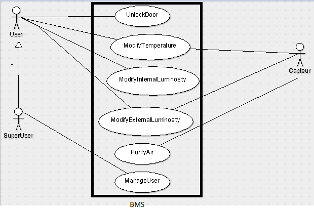
The users (User and SuperUser) are expected to be able to use keypads in order to identify themselves and LCD panel controls.
The SuperUser is expected to be the master of the system and will be more powerful than the User.
2.4 General constraints
The use of the BMS is directly linked to the activities which are done by the occupiers of the building.
The system will not include security monitor such as burglar's prevention but it will allow users to go inside the building by identifying themselves with the right codes.
2.5 Assumptions and dependencies
Building Management System (BMS) is the control system installed in buildings that controls and monitors the building’s mechanical and electrical.
This project implements parts of the BMS, for example, the control of the temperature, luminosity and quality of the air. The BMS is designed to large buildings, and this project is designed to houses.
3.Specific requirements, covering functional, non-functional and interface requirements
- document external interfaces,
- describe system functionality and performance
- specify logical database requirements,
- design constraints,
- emergent system properties and quality characteristics.
3.1 Requirement X.Y.Z (in Structured Natural Language)
Function:
The system allows the user to:
- Control the temperature;
- Control the luminosity;
- Control the quality of the air;
- Store the preferences user;
- Count the number of people in the house.
Description:
Inputs:
- The user data;
- The data from sensors:
-Sensor of temperature;
-Sensor of luminosity;
-Sensor of quality of the air.
Source:
- Sensor of temperature;
- Sensor of luminosity;
- Sensor of quality of the air;
- User.
Outputs:
- Visualization of data on the screen of the tablet.
- LED access indicator in the home.
Destination:
Action:
- Natural language sentences (with MUST, MAY, SHALL)
- Graphical Notations : UML Sequence w/o collaboration diagrams, Process maps, Task Analysis (HTA, CTT)
- Mathematical Notations
- Tabular notations for several (condition --> action) tuples
Non functional requirements:
Pre-condition:
Post-condition:
Side-effects:
4. Product evolution
- Builded a mini house model, where will be implanted the BMS.


