Proj-2013-2014-BrasRobot-Handicap-1
Description and Goals
The long-term goal of this project is to develop a control software manipulator arm for support of persons with disabilities.
Team
- Supervisor: Olivier Richard
- El Hadji Malick FALL, Adji Ndèye Ndaté SAMBE
- Department : RICM 4, Polytech Grenoble
Related Documents
- The Software Requirements Specification (SRS) can be found
- SPADE's user manual
- Github repository : [1]
Steps
The projet was attributed on Monday 13th and started the following day January 14th, 2014
Week 1 (January 13th - Janurary 19th)
- Project discovery
- Meeting with the different members of the project for assigning roles. Each pair chooses the part of the project that it wants to process.We choose to process the part on the detection of markers.
- Research on marker detection
Week 2 (January 20th - Janurary 26th)
- Test configuration of the robot
- Learning of C++
- Discovery of OpenCV
In details, we looked at the record and the code of the former group and studied the methods they proposed for the markers detection including hough transform and harritraining. Then we make some researchs to know how OpenCv works. One of the question is what will be the criteria of the markers : color, shape of both.
Week 3 (January 27th - February 2nd)
- Discovery of ArUco
ArUco is a minimal library for Augmented Reality applications based on OpenCv. One of its features of ArUco is Detect markers with a single line of C++ code. This will be very useful for our approach. As it is described in the source forge website, each marker has an unique code indicated by the black and white colors in it. The library detect borders, and analyzes into the rectangular regions which of them are likely to be markers. Then, a decoding is performed and if the code is valid, it is considered that the rectangle is a marker. So our next step will be to choose what kind of marker we will use and define the various steps of the recovery of the marker by the robot. We also start to learn Python langage which will be used to develop ArUco solution. Installing PyDev requires much more time as we though. After successfull completion, we are now developing our own solutions in Python inspired by ArUco's.
Week 4 (February 3rd- February 9th)
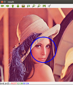
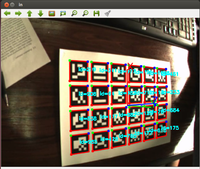
As we said, our own solutions are on going process. We expect that in this week they will be completed and fortunately we managed to make our first tests with ArUco. We have experienced a solution with black and white markers with ArUco, and a second with a face detection with OpenCV. The next step is now to be able to test it on video to first measure the efficiency and then take back the coordinates of marker's position that will be interesting for the system group.
Week 5 (February 10th- February 16th)
After a long trying, we have finally succeed to detect several markers contained in a jpeg picture and avi video. We are also able to get back the space coordinates of the marker. We could write it in a file that we will be used by the system team. Our next step is now to detect markers in a live video.
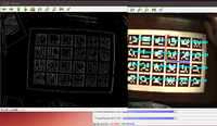
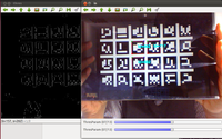
But even if Aruco solution is functional now, we can consider encounter some difficulties. For that OpenCV is still an optional solution. We have already made contact with the Canonball group about it. Knowing that we can retrieve the coordinates x, y, z of the marker, we expect, following our discussion with the group system, to transcribe these data into a text file they will use. The advantage of such a solution is that if the solution proposed by the system group is not practical, we can always use this file to prove the proper functioning of our solution and use it to find another alternative. In the meantime we do our first live detection tests. The first results are rather conclusive but now we will have to determine several scenarios that may happen.
Week 6 (February 17th- February 23th)
For this week, after making our first tests of real-time detection with our 1600x900 integrated webcam, we must renew them but this time with the webcam at our disposal. In Aruco, more generally in OpenCV, we have a type VideoCapture from the class of the same name that manages the video stream. It provides an open function whose signature is as follows:
0 is the default webcam of the computer and 1 the first outside webcam connected to the USB port. After making these changes, we are now able to use the webcam provided. Moreover, it should be noted that this phase of the project is a milestone. Before going further, we wanted to make an assessment of future solutions before integration. We first started to make a series of measures to evaluate the performance of detection.
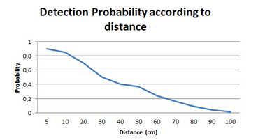
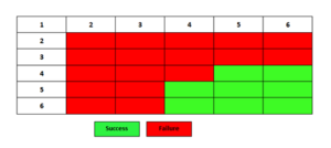
We find that the closer the distance, the greater the chances of detecting a marker. The optimal distance is estimated at 14 cm or less with our integrated webcam , and that under favorable conditions ( well calibrated light, visible marker) . We also conducted tests on the number of markers needed . We generated a matrix of markers and we tested detection :
Detecting a single marker might fail for different reasons such as poor lightning conditions, fast camera movement, occlusions, etc. To overcome that problem, ArUco allows the use of boards. An Augmented Reality board is a marker composed by several markers arranged in a grid. Boards present two main advantages. First, since there have more than one markers, it is less likely to lose them all at the same time. Second, the more markers are detected, the more points are available for computing the camera extrinsics. As a consecuence, the accuracy obtained increases.
We can see that the ideal would be to have a minimum size of 4x5 to ensure optimal detection . ie we are sure that at least one marker will be detected.
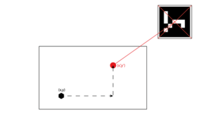
Based on these parameters, we can describe a first draft screenplay . The robot detects the marker. By applying the Pythagorean theorem , we can determine the coordinates of the central point. Once these coordinates obtained, the robot performs a translation to this point, as in the diagram below:
Week 7 (February 24th- March 2nd)
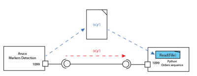
During this week we have improved the scenario drawn up last week. After identifying the actions that the robot will perform, we will now look at another problem: how the robot will know the coordinates of the point to be reached?
We considere two possible solutions:
- Write the coordinates on a file and parse it
- Transmit the coordinates through a socket
Both solutions are feasible but the second solution seems more interactive. The first was carried out, while the second is still in progress.
Week 8 (March 3rd- March 9th)
Educational truce
Week 9 (March 10th- March 16th)
The results of the marker detection are edited in a text file. To send the recovered data, we decided to convert this file into a XML file in python. That may facilitate reading and data retrieval. To do this, we used the python module xml.dom. Here is an excerpt from an example of a XML file with the coordinates of the detected marker:
<?xml version="1.0" ?>
<coordonnees>
: <p1 x="236.551" y="230.127"/>
: <p2 x="239.44" y="176.346"/>
: <p3 x="293.506" y="178.652"/>
: <p4 x="290.598" y="232.49"/>
</coordonnees>
As a marker is a square :
- p1 represents the coordinates of the bottom left.
- p2 represents the coordinates of the top left.
- p3 represents the coordinates of the top right.
- p4 represents the coordinates of the bottom right.
We also documented about the implementation of sockets with the client/server model in python for sending data. We tested several libraries proposed for the implementation of this solution.We realized that this solution was then feasible. So we began the implementation of this solution.
Week 10 (March 17th- March 23th)
We continued the implementation of sockets. After meeting with the second group, we noticed that the method we used seemed complicated. Therefore, we contacted our distributed applications teacher M. Philippe MORAT trying to see if there exists a way to do otherwise and more simpler. Following a discussion with him and thanks to the practical work on the system of agents in Java, we decided to use the model with agents because this model cut off from any language and is one of model of low-level simulations based on a channel.
We have also proposed this solution to the 2nd group who approved it.
Week 11 (March 24th- March 30th)
After much consideration with the second group, we decided to realize the previously proposed solution.
A multi-agent system (MAS) is a system composed of a set of agents located in a certain environment and interacting according to some relations. An agent is featured by its autonomous. It may be coded in the most known communication languages. The AAA model(Agent Anytime Anywhere) in Java is one of the best known. This solution has many advantages:
- not having to worry about the addresses and listening ports
- a easiness to create behaviors without worrying threads
- a easiness to send strings in the ACL (Agent Communication Language) and retrieve these strings. Serialized data, XML,... can also be sent
- the agent deployment and referencing the Directory Facilitator (directory of agents) is automatic. When an agent disappears, it is removed from the Directory Facilitator.
However, to maintain compliance with a requirement of the specifications that was to use the Python language, we conducted a series of studies which took us to the discovery of SPADE.
SPADE is a platform infrastructure development written in Python and based on the paradigm of multi-agent system. SPADE is based on the XMPP/Jabber protocol. Thus, a Python agent can very well communicate with C + + or Java agent for example. The agent may take any decisions alone or in groups. Each agent has an assigned task (a behavior) which is actually a kind of thread. One could imagine, for example an agent having behavior to send commands to other agents, as well as behavior to retrieve the results.
We therefore conducted various tests of this platform to determine how to adapt the functionalities offered by SPADE in our context of use.
Week 12 (March 31th- April 6th)
In this new stage, we began the implementation of a client/server model based on agents using the SPADE platform in python. The goal is to transfer the data of the XML file obtained in week 9. We proceed as follows:
- We create a client and server in python.
- The client opens and reads through the XML file and sends its contents line by line to the server as a sequence of messages.
- Upon receipt of these messages, the server in turn creates a new xml file in which it stores all recovered messages while respecting their order of receipt.
We wanted to make it simpler by sending the XML file directly to the server but we did not succeed. The Spade Module is not much used, it was difficult for us to find answers to our questions. We sent an email to developers but we remain still unanswered.
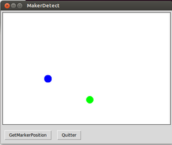
- We have subsequently made the development of a GUI that may simulate the behavior of the robotic arm after detection of the marker. To do this, we used the python module Tkinter. In our simulator, we represent the robot by a blue circle and a marker by a green circle. Thus, in the interface, the marker position is retrieved from the XML file provided by the server. The robot is then guided to this destination from the keyboard.
Week 13 (April 7th- April 09th)
In order to optimize the code provided, we conducted several modification. Instead of creating the XML file as explained in week 9, the client behaves as follows:
- read the file in text format directly returned by Aruco
- parse the file
- create the corresponding XML file
- send the data as explained above to the server
- server behavior meanwhile remains unchanged
This has simplified the steps and reduce the number of lines of code in the program.
- we started writing the report.
- we also made a preparation of the defense
- we cleaned the code
Appended
How to install Aruco
1- Install OpenCV first following this link http://miloq.blogspot.com.es/2012/12/install-opencv-ubuntu-linux.html
2- Then install aruco with http://miloq.blogspot.fr/2012/12/install-aruco-ubuntu-linux.html
How to install SPADE
There exists different ways to get SPADE module for python on Ubuntu /Debian
pip install SPADE or easy_install SPADE
If we want to install the platform from source grab the SPADE deliverable package at http://spade2.googleprojects.com or from the Python Package Index http://pypi.python.org/pypi/SPADE. Uncompress it and launch the setup.py script with the install parameter
$ tar xvzf SPADE-2.1.tar.gz
$ cd spade
$ python setup.py install
How to install Tkinter module for python
sudo apt-get install python python-tk idle python-pmw python-imaging
