Developing IoT Mashups with Docker, MQTT, Node-RED, InfluxDB, Grafana: Difference between revisions
| Line 1,554: | Line 1,554: | ||
</pre> |
</pre> |
||
[[Image:nodered-leaflet-flow.png| |
[[Image:nodered-leaflet-flow.png|400px|center|My Lab]] |
||
<pre> |
<pre> |
||
Revision as of 20:44, 1 December 2017
Page for the tutorial " Developing IoT Mashups with Docker, MQTT, Node-RED, InfluxDB, Chronograf, Grafana " at Eclipse IoT Days Grenoble 2016

Introduction
The goal of this tutorial is building rapidly a minimal IoT stack from sensors to dataviz and realtime analytics.
The hardware compoments used in this stack are:
- various (wireless) sensors,
- USB radio modems plugged into embedded IoT gateways,
- Raspberry Pi 1 and 2 playing the role of embedded IoT gateways,
- Your PC/Mac playing the role of the IoT datacenter server,
- A t2 micro AWS instance playing the role of the IoT datacenter server if a public IP address is required (case for Sigfox callback).
The software compoments used in this IoT stack are :
- Docker,
- Node.js and NPM,
- Node-RED and node contributions,
- Mosquitto
- InfluxDB
- MongoDB
- Chronograf
- Grafana (not on RPI)
- Spark (not on RPI)
Those software compoments are preinstalled on the Raspian Jessie distribution of the Raspberry PI boards in order to speed the installation and prevent WiFi whims.
Tools are:
Security, Avaibility and Performance issues are not in the scope of this tutorial.
Radio communication technologies are : Wifi, BLE, LoRa, SigFox, NFC and Rfxcom 433 MHz.
Info: the username and password on the RPIs are pi and IoTTraining
Install Docker
MacOS and Debian
See Docker
Raspian
wget --no-check-certificate https://downloads.hypriot.com/docker-hypriot_1.10.2-1_armhf.deb
sudo dpkg -i docker-hypriot_1.10.2-1_armhf.deb
sudo service docker restart
sudo docker info
Install Node.js and NPM
http://nodered.org/docs/hardware/raspberrypi
On Raspian Jessie : Node.JS is already installed but NPM not
nodejs -v
sudo apt-get update
sudo apt-get install npm
npm -v
On Raspian Wheezy
sudo apt-get update
sudo apt-get install nodejs npm
nodejs -v
npm -v
On MacOS X
TODO
With Docker
docker pull node
See https://hub.docker.com/_/node/
Install Node-RED
http://nodered.org/docs/hardware/raspberrypi
On Raspian Jessie : Node-RED is already installed (but you can update it with sudo apt-get update ; sudo apt-get install nodered)
node-red-start
pgrep node-red
The default directory is : ~/.node-red
Use node-red-stop to stop Node-RED
Use node-red-start to start Node-RED again
Use sudo systemctl enable nodered.service to autostart Node-RED at every boot
Use sudo systemctl disable nodered.service to disable autostart on boot
Browse http://127.0.0.1:1880/
Now, you can write your own Node-RED flows and functions.
Install the admin cmdline tool
sudo npm install -g node-red-admin
node-red-admin help

# installed modules
node-red-admin list


# search modules
node-red-admin search serial
node-red-admin search rfxcom
node-red-admin search zwave
node-red-admin search ble
node-red-admin search bluetooth
node-red-admin search sensortag

node-red-admin search beaglebone
node-red-admin search gpio

node-red-admin search mongodb
node-red-admin search redis
node-red-admin search cassandra
node-red-admin search elastic
node-red-admin search influxdb
node-red-admin search kafka
Remark: node-red-admin install <module> does not work ! Use npm install -g module
cd ~/.node-red
sudo npm install -g node-red-node-redis
sudo npm install -g node-red-contrib-kafka-consumer
sudo npm install -g node-red-node-mongodb
Restart Node-Red
node-red-admin list
With Docker
docker pull nodered/node-red-docker
Install extra nodes for Node-RED
Extra nodes are provided with the Node-RED community. There are listed here.
Serial for Geiger Counter

Install the serial node (node-red-node-serialport)
npm install node-red-node-serialport
or
sudo npm install -g npm@2.x
npm install node-red-node-serialport@0.0.5
if node.js prior to 4.x (ie v0.10.x and v0.12.x)
Restart Node-RED with node-red -v.
Check the module in the list
node-red-admin list | grep serial
Check available serial ports (/dev/tty.usbserial* on MacOS X, /dev/ttyUSB* ...) with ls /dev/tty.*.
Connect the Geiger counter to the host.
Check available serial ports (/dev/tty.usbserial* on MacOS X, ...) with ls /dev/tty.*.
Add a node serial "Geiger" with a Settings of 9600/8/N/1 and 'Split input into fixed lenghts of 1 chars'.
Add a node debug.
Connect "Geiger" to debug.
Deploy the flow.
The Geiger Counter sends a random sequence of 0 and 1.
Add a node function "Count Particles" with a flow-scoped variable (geiger/count):
var COUNT='geiger/count';

// initialise the counter to 0 if it doesn't exist already
var count = flow.get(COUNT)||0;
count += 1;
// store the value back
flow.set(COUNT,count);
// make it part of the outgoing msg object
msg.count = count;
msg.payload = {};
msg.payload.device = "geiger";
msg.payload.count = count;

node.log("Received particles : " + count);

return msg;
Connect node "Geiger" to node "Count Particles".
Deploy the new flow.
Edit the node "Count Particles" and add the 2 following statements in order to display the count into the node's status.
...
setTimeout(function() { node.status({}); }, 1000);
// The shape property can be: ring or dot.
// The fill property can be: red, green, yellow, blue or grey
node.status({fill:"green",shape:"dot",text:"#"+count});
return msg;
Deploy the new flow.
Add a node inject "One minute timer" with a repeat interval of 1 minute.
Add a node function "Reset Particles Count" with a flow-scoped variable (geiger/count):
var COUNT='geiger/count';

// initialise the counter to 0 if it doesn't exist already
var count = flow.get(COUNT)||0;

msg.count = count;
msg.payload = {};
msg.payload.device = "geiger";
msg.payload.ppm = count;

node.log("Reset counter at " + count);

// make it part of the outgoing msg object
count = 0;
// store the value back
flow.set(COUNT,count);

return msg;
Connect node "One minute timer" to node "Reset Particles Count" and node "Reset Particles Count" to node debug.
Deploy the new flow.
The result is:

RFXCom for Oregon Weather Sensors
Install the rfxcom node (node-red-contrib-rfxcom)
cd ~/.node-red
npm install -g node-red-contrib-rfxcom
Restart Node-RED with node-red -v.
Check the module in the list
node-red-admin list | grep rfx
Connect the RFXCom receiver to the host.
Check available serial ports (/dev/tty.usbserial* on MacOS X, ...) with ls /dev/tty.*.
Add a node rfxcom-sensors "RFXCom" with the correct serial port.
Add a node debug display the full message (not only msg.payload).
Connect "RFXCom" to debug.
Deploy the flow.
The flow loos like that:


Serial for Arduino + Weather Shield

Plug the SparkFun Weather Shield into the Arduino Leonardo. Connect the Weather Meters to the shield sockets.
Install the Arduino IDE on your host (link)
Install 2 extra libraries (Menu Sketch > Include Library > Add ZIP Library)
- https://codeload.github.com/sparkfun/SparkFun_HTU21D_Breakout_Arduino_Library/zip/master
- https://codeload.github.com/sparkfun/SparkFun_MPL3115A2_Breakout_Arduino_Library/zip/master
Select the right board (Arduino Leonardo) with the menu Tool
Load and unzip the Weather_Shield sketch bundle https://codeload.github.com/sparkfun/Weather_Shield/zip/master
Load the sketch Weather_Shield/firmware/Weather_Shield/Weather_Shield.ino into the Arduino Leonardo
Check the output with the menu Tool > Serial Monitor
The output looks like this:
$,winddir=-1,windspeedmph=3.1,windgustmph=117.7,windgustdir=-1,windspdmph_avg2m=3.1,winddir_avg2m=0,windgustmph_10m=117.7,windgustdir_10m=-1,humidity=33.6,tempf=75.2,rainin=3.04,dailyrainin=3.04,pressure=98257.75,batt_lvl=4.28,light_lvl=0.28,#
Install the serial node (node-red-node-serialport)
npm install node-red-node-serialport
or
sudo npm install -g npm@2.x
npm install node-red-node-serialport@0.0.5
if node.js prior to 4.x (ie v0.10.x and v0.12.x)
Restart Node-RED with node-red -v.
Check the module in the list
node-red-admin list | grep serial
Check available serial ports (/dev/tty.usbserial* on MacOS X, /dev/ttyUSB* ...) with ls /dev/tty.*.
Start Node-RED
node-red -v
Add a node debug
Add a node function "Clean Data" with the following statements:
var m=msg.payload;
var i=m.indexOf(",")+1;
msg.payload=m.substr(i,m.lastIndexOf(",")-i);
setTimeout(function() { node.status({}); }, 500)
node.status({fill:"green",shape:"dot",text:"updated"});
return msg;
Add a node serial "Weather Station" with settings 9600/8/N/1 and split input on charracter /n
Connect them together like that

The flow is :
[{"id":"40c61a94.428894","type":"serial-port","z":"65e2c142.626cf8","serialport":"/dev/tty.usbmodem1451","serialbaud":"9600","databits":"8","parity":"none","stopbits":"1","newline":"\\n","bin":"false","out":"char","addchar":false},{"id":"e0626709.612a1","type":"serial in","z":"65e2c142.626cf8","name":"Weather Station","serial":"40c61a94.428894","x":200.5,"y":486.5,"wires":[["576a5389.61c4e4"]]},{"id":"bf78bff1.63e8a","type":"debug","z":"65e2c142.626cf8","name":"","active":true,"console":"false","complete":"payload","x":802.5,"y":488,"wires":[]},{"id":"576a5389.61c4e4","type":"function","z":"65e2c142.626cf8","name":"Clean data","func":"var m=msg.payload;\nvar i=m.indexOf(\",\")+1;\nmsg.payload=m.substr(i,m.lastIndexOf(\",\")-i);\nsetTimeout(function() { node.status({}); }, 500)\nnode.status({fill:\"green\",shape:\"dot\",text:\"updated\"});\nreturn msg;","outputs":1,"noerr":0,"x":498.5,"y":486.5,"wires":[["bf78bff1.63e8a"]]}]
Serial for LoRa Libelium


Install the Waspmote PRO IDE from Libelium on your host (link)
Load the sketch SX_02a_TX_LoRa on the LoRa Waspmote.
/*
 *  ------ [SX_02a] - TX LoRa --------
 *
 *  Explanation: This example shows how to configure the semtech
 *  module in LoRa mode and then send packets with plain-text payloads
 */
// Include this library to transmit with sx1272
#include <WaspSX1272.h>

// define the destination address to send packets
uint8_t rx_address = 8;

// status variable
int8_t e;

void setup()
{
  // Init USB port
  USB.ON();
  USB.println(F("SX_02a example"));
  USB.println(F("Semtech SX1272 module TX in LoRa"));

  USB.println(F("----------------------------------------"));
  USB.println(F("Setting configuration:"));
  USB.println(F("----------------------------------------"));

  // Init sx1272 module
  sx1272.ON();

  // Select frequency channel
  e = sx1272.setChannel(CH_10_868);
  USB.print(F("Setting Channel CH_10_868.\t state "));
  USB.println(e);

  // Select implicit (off) or explicit (on) header mode
  e = sx1272.setHeaderON();
  USB.print(F("Setting Header ON.\t\t state "));
  USB.println(e);

  // Select mode: from 1 to 10
  e = sx1272.setMode(1);
  USB.print(F("Setting Mode '1'.\t\t state "));
  USB.println(e);

  // Select CRC on or off
  e = sx1272.setCRC_ON();
  USB.print(F("Setting CRC ON.\t\t\t state "));
  USB.println(e);

  // Select output power (Max, High or Low)
  e = sx1272.setPower('L');
  USB.print(F("Setting Power to 'L'.\t\t state "));
  USB.println(e);

  // Select the node address value: from 2 to 255
  e = sx1272.setNodeAddress(2);
  USB.print(F("Setting Node Address to '2'.\t state "));
  USB.println(e);
  USB.println();

  delay(1000);

  USB.println(F("----------------------------------------"));
  USB.println(F("Sending:"));
  USB.println(F("----------------------------------------"));
}

void loop()
{
  // Sending packet before ending a timeout
  e = sx1272.sendPacketTimeout( rx_address, "This_is_a_new_message");

  // Check sending status
  if( e == 0 )
  {
    USB.println(F("Packet sent OK"));
  }
  else
  {
    USB.println(F("Error sending the packet"));
    USB.print(F("state: "));
    USB.println(e, DEC);
  }
  delay(2500);
}
Check with the IDE Serial monitor the output of the Waspmote
Load the sketch SX_02b_RX_LoRa on the LoRa Dongle.
/*
 *  ------ [SX_02b] - RX LoRa --------
 *  Explanation: This example shows how to configure the semtech
 *  module in LoRa mode and then receive packets with plain-text payloads
 */
// Include this library for transmit with sx1272
#include <WaspSX1272.h>

// status variable
int8_t e;

void setup()
{
  // Init USB port
  USB.ON();
  USB.println(F("SX_02b example"));
  USB.println(F("Semtech SX1272 module RX in LoRa"));

  USB.println(F("----------------------------------------"));
  USB.println(F("Setting configuration:"));
  USB.println(F("----------------------------------------"));

  // Init sx1272 module
  sx1272.ON();

  // Select frequency channel
  e = sx1272.setChannel(CH_10_868);
  USB.print(F("Setting Channel CH_10_868.\t state "));
  USB.println(e);

  // Select implicit (off) or explicit (on) header mode
  e = sx1272.setHeaderON();
  USB.print(F("Setting Header ON.\t\t state "));
  USB.println(e);

  // Select mode: from 1 to 10
  e = sx1272.setMode(1);
  USB.print(F("Setting Mode '1'.\t\t state "));
  USB.println(e);

  // Select CRC on or off
  e = sx1272.setCRC_ON();
  USB.print(F("Setting CRC ON.\t\t\t state "));
  USB.println(e);

  // Select output power (Max, High or Low)
  e = sx1272.setPower('L');
  USB.print(F("Setting Power to 'L'.\t\t state "));
  USB.println(e);

  // Select the node address value: from 2 to 255
  e = sx1272.setNodeAddress(8);
  USB.print(F("Setting Node Address to '8'.\t state "));
  USB.println(e);

  delay(1000);

  USB.println(F("----------------------------------------"));
  USB.println(F("Receiving:"));
  USB.println(F("----------------------------------------"));
}

void loop()
{
  // receive packet
  e = sx1272.receivePacketTimeout(10000);

  // check rx status
  if( e == 0 )
  {
    USB.println(F("\nShow packet received: "));

    // show packet received
    sx1272.showReceivedPacket();
  }
  else
  {
    USB.print(F("\nReceiving packet TIMEOUT, state "));
    USB.println(e, DEC);
  }
}
Check with the IDE Serial monitor the output of the USB Dongle
Install the serial node (node-red-node-serialport)
npm install node-red-node-serialport
or
sudo npm install -g npm@2.x
npm install node-red-node-serialport@0.0.5
if node.js prior to 4.x (ie v0.10.x and v0.12.x)
Restart Node-RED with node-red -v.
Check the module in the list
node-red-admin list | grep serial
Check available serial ports (/dev/tty.usbserial* on MacOS X, /dev/ttyUSB*, /dev/ttyAMA*, /dev/ttyACM* ...) with ls /dev/tty.*.
The RX boards receive LoRa frames and output the following lines on the console when the TX boards are powered :
...
SX_02b example
Semtech SX1272 module RX in LoRa
----------------------------------------
Setting configuration:
----------------------------------------
Setting Channel CH_10_868.	 state 0
Setting Header ON.		 state 0
Setting Mode '1'.		 state 0
Setting CRC ON.			 state 0
Setting Power to 'L'.		 state 0
Setting Node Address to '8'.	 state 0
----------------------------------------
Receiving:
----------------------------------------

Show packet received:
==============================
dest: 8
src: 2
packnum: 171
length: 26
retry: 0
payload (HEX): 546869735F69735F615F6E65775F6D657373616765
payload (string): This_is_a_new_message
==============================
...
Create a new flow or start Node-RED
Add a node debug
Add a node function "Extract RX Data" with the following statements
var prefix="payload (HEX): ";
var m=msg.payload;
var i=m.indexOf(prefix);
if(i===0) {
    msg.payload=new Buffer(m.substr(prefix.length),"HEX");
    setTimeout(function() { node.status({}); }, 500)
    node.status({fill:"green",shape:"dot",text:"updated"});
    return msg;
} else {
    return null;
}
Add a node serial "LoRa RX Modem" with settings 115200/8/N/1 and split input on character /n. On RPI, the port is /dev/ttyUSB0.
Connect them together like that
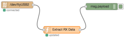

The flow is :
[{"id":"3124f278.d5cc86","type":"serial-port","z":"3cf8afc1.fe41a","serialport":"/dev/ttyUSB2","serialbaud":"115200","databits":"8","parity":"none","stopbits":"1","newline":"\\n","bin":"false","out":"char","addchar":false},{"id":"8ea9bd5f.7ffac8","type":"serial in","z":"3cf8afc1.fe41a","name":"","serial":"3124f278.d5cc86","x":123.5,"y":137.5,"wires":[["a9a605c3.664548"]]},{"id":"32a2d4e0.54214c","type":"debug","z":"3cf8afc1.fe41a","name":"","active":true,"console":"false","complete":"false","x":495.5,"y":145,"wires":[]},{"id":"a9a605c3.664548","type":"function","z":"3cf8afc1.fe41a","name":"Extract RX Data","func":"var prefix=\"payload (HEX): \";\nvar m=msg.payload;\nvar i=m.indexOf(prefix);\nif(i===0) {\n msg.payload=new Buffer(m.substr(prefix.length),\"HEX\");\n setTimeout(function() { node.status({}); }, 500)\n node.status({fill:\"green\",shape:\"dot\",text:\"updated\"});\n return msg;\n} else {\n return null;\n}","outputs":1,"noerr":0,"x":320.5,"y":247.5,"wires":[["32a2d4e0.54214c"]]}]
Serial for LoRaWAN Libelium

Install the Waspmote PRO IDE from Libelium on your host (link)
Load the sketch LoRaWAN_02_join_abp_send_unconfirmed (from Examples > 03. Communications > LoRaWAN) on the LoRaWAN Waspmote. (API documentation)
Add the following flow into the Node-RED server embedded in the Multitech gateway. This flow adapts the [Shttps://github.com/Lora-net/packet_forwarder/blob/master/PROTOCOL.TXT emtech packer forwarder protocol] to MQTT.
TBC
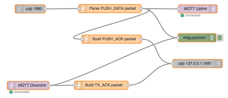

The flow is :
[{"id":"5bf2579.78cd328","type":"mqtt-broker","broker":"192.168.0.101","port":"1883","clientid":""},{"id":"b1939dd4.d3375","type":"debug","name":"","active":true,"console":"false","complete":"false","x":852,"y":951,"z":"bcbfaccb.6b341","wires":[]},{"id":"23420539.4f4012","type":"udp in","name":"","iface":"","port":"1680","ipv":"udp4","multicast":"false","group":"","datatype":"buffer","x":254,"y":847,"z":"bcbfaccb.6b341","wires":[["7c343386.1d5f5c"]]},{"id":"7c343386.1d5f5c","type":"function","name":"Parse PUSH_DATA packet","func":"// See https://github.com/Lora-net/packet_forwarder/blob/master/PROTOCOL.TXT\n\n/*\n### 3.2. PUSH_DATA packet ###\n\nThat packet type is used by the gateway mainly to forward the RF packets \nreceived, and associated metadata, to the server.\n\n Bytes | Function\n:------:|---------------------------------------------------------------------\n 0 | protocol version = 2\n 1-2 | random token\n 3 | PUSH_DATA identifier 0x00\n 4-11 | Gateway unique identifier (MAC address)\n 12-end | JSON object, starting with {, ending with }, see section 4\n*/\n\n\n\nvar from=msg[\"from\"];\nvar ip=msg[\"ip\"];\nvar fromip=msg[\"fromip\"];\n\nvar b = msg.payload;\n\nif(b.length < 12) return undefined;\n\nvar payload = {};\n\npayload[\"protocol\"] = b.readUInt8(0);\npayload[\"token\"] = b.readUInt16BE(1);\npayload[\"push_data_id\"] = b.readUInt8(3);\npayload[\"gateway_eui\"] = b.slice(4,12).toString(\"hex\");\nvar json = b.slice(12);\nif(json !== undefined && json.length > 0) {\n payload[\"json\"] = JSON.parse(json);\n}\n \n\nmsg.payload = payload;\nreturn msg;","outputs":1,"noerr":0,"x":540,"y":846,"z":"bcbfaccb.6b341","wires":[["b1939dd4.d3375","fadd4563.822ee8","36d9eb5c.4250d4"]]},{"id":"b38c07a5.0ae658","type":"udp out","name":"","addr":"127.0.0.1","iface":"","port":"1681","ipv":"udp4","outport":"","base64":false,"multicast":"false","x":854,"y":1044,"z":"bcbfaccb.6b341","wires":[]},{"id":"fadd4563.822ee8","type":"function","name":"Build PUSH_ACK packet","func":"// See https://github.com/Lora-net/packet_forwarder/blob/master/PROTOCOL.TXT\n\n/*\n### 3.3. PUSH_ACK packet ###\n\nThat packet type is used by the server to acknowledge immediately all the \nPUSH_DATA packets received.\n\n Bytes | Function\n:------:|---------------------------------------------------------------------\n 0 | protocol version = 2\n 1-2 | same token as the PUSH_DATA packet to acknowledge\n 3 | PUSH_ACK identifier 0x01\n*/\n\nvar payload = new Buffer(4);\n\npayload[0] = msg.payload.protocol;\npayload.writeUInt16BE(msg.payload.token,1);\npayload[3] = 0x01;\n\nmsg.payload = payload;\n\nreturn msg;","outputs":1,"noerr":0,"x":546,"y":956,"z":"bcbfaccb.6b341","wires":[["b38c07a5.0ae658"]]},{"id":"36d9eb5c.4250d4","type":"mqtt out","name":"MQTT Uplink","topic":"gateway/up/008000000000aaaa","qos":"","retain":"","broker":"5bf2579.78cd328","x":855,"y":847,"z":"bcbfaccb.6b341","wires":[]},{"id":"e6274e97.c4455","type":"mqtt in","name":"MQTT Downlink","topic":"gateway/dn/008000000000aaaa","broker":"5bf2579.78cd328","x":247,"y":1123,"z":"bcbfaccb.6b341","wires":[["84741d8f.12f3c8","b1939dd4.d3375"]]},{"id":"84741d8f.12f3c8","type":"function","name":"Build TX_ACK packet","func":"// See https://github.com/Lora-net/packet_forwarder/blob/master/PROTOCOL.TXT\n\n/*\n### 5.5. TX_ACK packet ###\n\nThat packet type is used by the gateway to send a feedback to the server\nto inform if a downlink request has been accepted or rejected by the gateway.\nThe datagram may optionnaly contain a JSON string to give more details on\nacknoledge. If no JSON is present (empty string), this means than no error\noccured.\n\n Bytes | Function\n:------:|---------------------------------------------------------------------\n 0 | protocol version = 2\n 1-2 | same token as the PULL_RESP packet to acknowledge\n 3 | TX_ACK identifier 0x05\n 4-end | [optional] JSON object, starting with {, ending with }, see section 6*/\n\nvar payload = new Buffer(4+msg.payload.length);\n\npayload[0] = 2;\n\nmsg.payload.protocol;\n//payload.writeUInt16BE(msg.payload.token,1);\npayload[3] = 0x05;\nmsg.payload.copy(payload,4);\n\nmsg.payload = payload;\n\nreturn msg;","outputs":1,"noerr":0,"x":509,"y":1122,"z":"bcbfaccb.6b341","wires":[["b38c07a5.0ae658"]]}]
Test with mosquitto_sub -t "gateway/up/#" -d
Serial for LoRa Nucleo

Install the serial node (node-red-node-serialport)
npm install node-red-node-serialport
or
sudo npm install -g npm@2.x
npm install node-red-node-serialport@0.0.5
if node.js prior to 4.x (ie v0.10.x and v0.12.x)
Restart Node-RED  with node-red -v.
Check the module in the list
node-red-admin list | grep serial
Check available serial ports (/dev/tty.usbserial* on MacOS X, /dev/ttyUSB*, /dev/ttyAMA*, /dev/ttyACM* ...) with ls /dev/tty.*.
Compile and load the SX1276Receiver program https://developer.mbed.org/users/donsez/code/SX1276Receiver/ on the Nucleo board.
For the receiver, set line 16 to  #define RX_MODE 1
For the transmitter, set line 16 to  #define RX_MODE 0
Remark: select the right board (F411 or L152 for instance).
The RX boards receive LoRa frames and output the following lines on the console when the TX boards are powered :
...
>INFO RX modem=1 size=17 rssi=-41 snr=31 freq=868100000 bw=0 sf=12 cr=1 buffer=544553540004411d616263646566676869
RX;1;17;-41;31;868100000;0;12;1;544553540004411d616263646566676869
...
Create a new flow or start Node-RED
Add a node debug
Add a node function "Extract RX Data" with the following statements
var prefix="RX;";
var m=msg.payload;
var i=m.indexOf(prefix);
if(i===0) {
    msg.payload=m.substr(prefix.length);
    setTimeout(function() { node.status({}); }, 500)
    node.status({fill:"green",shape:"dot",text:"updated"});
    return msg;
} else {
    return null;
}
Add a node serial "LoRa RX Modem" with settings 115200/8/N/1 and split input on character /n. On RPI, the port is /dev/ttyACM0.
Connect them together like that
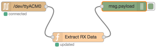

The flow is :
TODO
UDP for LoRaWAN
Add a node 'udp in' listening the port 8123.
Add a node 'function' "toString" with the following statement:
msg.payload=msg.payload.toString();
return msg;
Add a node 'debug'.
Connect them together.
Deploy the new flow.
Test the flow with the shell command
echo -n -e '{"device"="123456","temperature"=37.2}' > /dev/udp/127.0.0.1/8123
The flow looks like that:


Add a node 'json' into the flow.
Now you can filter and send the output of a process to the flow througth an 'udp in' node.
TO BE CONTINUED
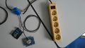
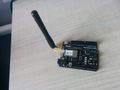
UDP for ESP8266 + PowerSensor


Install the Arduino IDE on your host (link)
Add the "ESP8266 Modules" support with the Tools menu > Board Manager.
Select "NodeMCU 0.9 (ESP8266-12 Module)" in the Tools menu.
Load the following sketch on the ESP8266.
/*
From http://www.iotfrog.com/en/articles/article/227
*/

#include <ESP8266WiFi.h>
#include <WiFiUDP.h>

const char* ssid     = "iotdays";
const char* password = "eclipse2016";

//IPAddress ipBroadCast(192,168,1,255);
IPAddress ipBroadCast;

unsigned int udpRemotePort = 8123;
unsigned int udplocalPort = 8124;
const int UDP_PACKET_SIZE = 48;

char udpBuffer[ UDP_PACKET_SIZE];
WiFiUDP udp;

// Setup the Wifi connection
void connectWifi() {
  Serial.print("Connecting to ");
  Serial.println(ssid);

  //  Try to connect to wifi access point
  WiFi.begin(ssid, password);
  while (WiFi.status() != WL_CONNECTED) {
    delay(500);
    Serial.print(".");
  }
  Serial.println("");
  Serial.println("WiFi connected");
  Serial.print("IP address: ");
  Serial.println(WiFi.localIP());

  ipBroadCast = ~WiFi.subnetMask() | WiFi.gatewayIP();
}

// Send udp message
void udpSend()
{
  // TODO read the current value of an analog pin

  strcpy(udpBuffer, "{\"device\"=\"12348266\",\"load\"=10.2}");
  udp.beginPacket(ipBroadCast, udpRemotePort);
  udp.write(udpBuffer, sizeof(udpBuffer));
  udp.endPacket();
  Serial.print("Broadcast: ");
  Serial.println(udpBuffer);
}

// Setup hardware, serial port, and connect to wifi.
void setup() {
  Serial.begin(115200);
  delay(10);
  // We start by connecting to a WiFi network
  connectWifi();

  Serial.println("Starting UDP");
  // set udp port for listen
  udp.begin(udplocalPort);
  Serial.print("Local port: ");
  Serial.println(udp.localPort());
}

// LOOP MAIN
// Send udp packet each 10 secconds
void loop() {
  udpSend();
  delay (10000);
}
Add a node 'udp in' listening the port 8123 with a Buffer output.
Add a node 'function' "toStr" with the following statement:
msg.payload=msg.payload.toString();
return msg;
Add a node 'debug'.
Connect them together.
Deploy the new flow.
The flow looks like that:
Remark: you can test the flow with this shell command
echo -n -e '{"device"="12348266","load"=10}' > /dev/udp/127.0.0.1/8123
The flow is:
[{"id":"b32d523b.fd02d8","type":"udp in","z":"a994a424.14415","name":"","iface":"","port":"8123","ipv":"udp4","multicast":"false","group":"","datatype":"utf8","x":147,"y":94,"wires":[["1658af1a.ebfd11"]]},{"id":"f732d1c6.93623","type":"debug","z":"a994a424.14415","name":"","active":true,"console":"false","complete":"payload","x":535,"y":94.5,"wires":[]},{"id":"1658af1a.ebfd11","type":"function","z":"a994a424.14415","name":"toStr","func":"setTimeout(function() { node.status({}); }, 1000);\n// The shape property can be: ring or dot.\n// The fill property can be: red, green, yellow, blue or grey\nnode.status({fill:\"green\",shape:\"dot\",text:\"receiving\"}); \nmsg.payload=msg.payload.toString();\nreturn msg;","outputs":1,"noerr":0,"x":336,"y":94,"wires":[["f732d1c6.93623"]]}]
Second part:
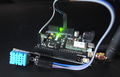
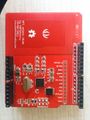
Plug the SCT-013 Current Clamp power shield into the ESP8266 Arduino board.
Compile and load the following sketch on the ESP8266 Arduino board.
#include <ESP8266WiFi.h>          //https://github.com/esp8266/Arduino

//needed for library
#include <DNSServer.h>
#include <ESP8266WebServer.h>
#include <stdlib.h>
#include "EmonLib.h"             // Include Emon Library

EnergyMonitor emon1;             // Create an instance
const int ANALOG_PIN = A0; // The only analog pin on the Thing

const char host[] = "52.50.55.74";
const int port = 80;
const char nodename[] = "sct013";
const char apiKey[] = "&apikey=7af3b1772fa1b624ef73925ba117d562";


const char* ssid     = "iotdays";
const char* password = "eclipse2016";

// Use WiFiClient class to create TCP connections
WiFiClient client;


void setup()
{
  Serial.begin(115200);
  delay(10);


  // We start by connecting to a WiFi network

  Serial.println();
  Serial.println();
  Serial.print("Connecting to ");
  Serial.println(ssid);
  WiFi.begin(ssid, password);

  while (WiFi.status() != WL_CONNECTED) {
    delay(500);
    Serial.print(".");
  }

  Serial.println("");
  Serial.println("WiFi connected");
  Serial.println("IP address: ");
  Serial.println(WiFi.localIP());
  emon1.current(A0, 29.1);       // Current: input pin, calibration.
}

void loop()
{
  Serial.print("waiting a delay\n");
  delay(5000);

  Serial.print("connecting to ");
  Serial.println(host);

  double Irms = emon1.calcIrms(1480);  // Calculate Irms only
  Serial.println("begin loop");

  const int httpPort = 80;
  if (!client.connect(host, httpPort)) {
    Serial.println("connection failed");
    return;
  }

  // This will send the request to the server
  const String url =  "/input/post.json?node=" + String(nodename) + "&json={power:" + String(Irms * 1.414 * 235 / 10) + "}" + String(apiKey);
  client.print("GET " + url + " HTTP/1.1\r\n" +
               "Host:" + host + "\r\n" +
               "Connection: close\r\n\r\n");
  Serial.print("Requesting URL: ");
  Serial.println(url);

  delay(10);

  // Read all the lines of the reply from server and print them to Serial
  while (client.available()) {
    String line = client.readStringUntil('\r');
    Serial.print(line);
  }

  Serial.println();
  Serial.println("closing connection");
}
Change the Node-RED to display the received data.
-
-


Third part: Change the shetch in order to use MQTT for the message transport : see https://github.com/tuanpmt/esp_mqtt
ACR122U NFC Reader
Plug the ACR122U NFC reader in the host and check it with lsusb
Install LibNFC (on Debian)
sudo apt-get install libnfc-dev libnfc-bin libnfc-examples
sudo nfc-list
Launch nfc-poll and put a NFC card/tag on the reader
sudo nfc-poll -v
The ID of the NFC card/tag is prefixed by the string UID (NFCID1):.
Execute the following script sudo ./nfcevent.sh:
#!/bin/sh
while true
do
    nfc-poll | grep "UID (NFCID1):" > /tmp/nfc.log
done
Into the Node-RED dashboard, create a new flow.
Add a node tail for reading the tail of the log file containing the card/tags identifiers.
Add a node debug.
Connect the node tail to the node debug.
Deploy the new flow.
Add a node function "Build message" with the following statements:
var m=msg.payload;
var i=m.indexOf(":");
if(i>=0) {
    var tid = m.substr(i+1).replace(/\s+/g, '');
    msg.payload={}
    msg.payload.device="acr122u";
    msg.payload.nfc=tid;
    return msg;
}
return null;
Connect the node tail to the node "Build message" and the node "Build message"  to the node debug.
Deploy the new flow.


Edit the node "Build message" and add the 2 following statements in order to display the last tid into the node's status during one second.
    ...
    setTimeout(function() { node.status({}); }, 1000);
    // The shape property can be: ring or dot.
    // The fill property can be: red, green, yellow, blue or grey
    node.status({fill:"green",shape:"dot",text:"#"+tid});
    return msg;
}
return null;
Deploy the new flow.
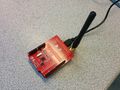
Sigfox Weather Station : Sigfox Areku Board + DHT11
Connect the DHT11 pins into the Areku board pins (or the Akene shield with an Arduino or STM32 Nucleo boards).
- + --> 5V
- - --> GND
- OUT --> D2
Install the libraries Areku and DHT11 libraries into the Arduino IDE.
Compile and load the following sketch into the Areku board. The board type of the Areku board is "Uno".
#include <SoftwareSerial.h>
#define RX_PIN 5
#define TX_PIN 4

#include "DHT.h"

#define DHTPIN 2     // what pin we're connected to

// Uncomment whatever type you're using!
#define DHTTYPE DHT11   // DHT 11
//#define DHTTYPE DHT22   // DHT 22  (AM2302)
//#define DHTTYPE DHT21   // DHT 21 (AM2301)

// Connect pin 1 (on the left) of the sensor to +5V
// Connect pin 2 of the sensor to whatever your DHTPIN is
// Connect pin 4 (on the right) of the sensor to GROUND
// Connect a 10K resistor from pin 2 (data) to pin 1 (power) of the sensor

DHT dht(DHTPIN, DHTTYPE);

SoftwareSerial sigfox(RX_PIN,TX_PIN);

// Sigfox message size is 12 bytes max.
#define BUFFERSIZE 256
char downlinkbuffer[BUFFERSIZE];

// Send message every 11 minutes (max 140 messages per day)
#define PERIOD 660000

void getDownlinkLine(char * buffer)
{
  uint8_t idx = 0;
  char c;
  do
  {
    while (sigfox.available() == 0) ; // wait for a char this causes the blocking
    c = sigfox.read();
    buffer[idx++] = c;
  }
  while (c != '\n' && c != '\r' && idx >= BUFFERSIZE);
  buffer[idx] = 0;
}

void setup(){
  Serial.begin(9600);
  sigfox.begin(9600);
  dht.begin();
}

void loop(){
  // Reading temperature or humidity takes about 250 milliseconds!
  // Sensor readings may also be up to 2 seconds 'old' (its a very slow sensor)
  float fh = dht.readHumidity();
  float ft = dht.readTemperature();

  // check if returns are valid, if they are NaN (not a number) then something went wrong!
  if (isnan(ft) || isnan(fh)) {
    Serial.println("Failed to read from DHT");
  } else {
    Serial.print("Temperature: ");
    Serial.print(ft);
    Serial.println(" *C");
    Serial.print("Humidity: ");
    Serial.print(fh);
    Serial.println(" %\t");

    Serial.print("Send message\n");
    sigfox.write("AT$SF=");

    sigfox.print((byte)ft, HEX);
    sigfox.write(" ");
    sigfox.print((byte)fh, HEX);

    sigfox.write("\n");

    getDownlinkLine(downlinkbuffer);
    Serial.print(downlinkbuffer);
    Serial.print("\n");

    Serial.print("Wait ");
    Serial.print(PERIOD/1000);
    Serial.print(" second before next uplink\n");

  }
  delay(PERIOD);
 }
Check with the IDE Serial monitor the USB output of the board.
Install and run the following Node.js script:
var PORT = 3000;
var PATH = '/sigfox';

//var BROKER_URL = "mqtt://localhost";
var BROKER_URL = "mqtt://test.mosquitto.org";
var TOPIC = "iotdays/sensors/sigfox";

var express = require('express');
var app = express();

var mqtt    = require('mqtt');
var client  = mqtt.connect(BROKER_URL);
var mqttConnected = false;

client.on('connect', function () {
  mqttConnected = true;
  console.log('Sigfox callback server : MQTT connected to ',BROKER_URL);
});

client.on('reconnect', function () {
  mqttConnected = true;
  console.log('Sigfox callback server : MQTT reconnected to ',BROKER_URL);
});

client.on('offline', function () {
  mqttConnected = false;
  console.log('Sigfox callback server : MQTT offline ');
});

client.on('close', function () {
  mqttConnected = false;
  console.log('Sigfox callback server : MQTT closed');
});

client.on('error', function (error) {
  mqttConnected = false;
  console.log('Sigfox callback server : MQTT Error ',error);
});


app.get(PATH, function (req, res) {
  console.log("Received ", JSON.stringify(req.query));
  if(mqttConnected) {
	client.publish(TOPIC, JSON.stringify(req.query));
	res.send('Callback received');
  } else {
  	res.status(500).send('Could not delivered callback');
  }
});

app.listen(PORT, function () {
  console.log('Sigfox callback server listening on port ', PORT);
});
npm init
npm install express --save
sudo npm install mqtt --save
cat package.json
node server.js
Configure the callback http://52.50.55.74:3000/sigfox?data={data}&id={device}&time={time}&snr={snr}&station={station}&avgSnr={avgSnr}&rssi={rssi}&lat={lat}&lng={lng}&seqNumber={seqNumber}&duplicate={duplicate} for the device into the Sigfox backend. (account is required)
Create a flow with a MQTT in node and a debug node.
Parse and display the values sent by the Sigfox backend : device, time, duplicate, snr, station, data, avgSnr, lat, lng, rssi, seqNumber
TBC
Remarks:
- The Sigfox modem can not send more than 144 messages due to the ETSI regulation.
- A Sigfox message contains up to 12 bytes (authenticated but not encrypted)
-
-
-


Sigfox Patrol Man : Sigfox Areku Board + Sparkfun's Weather Station Shield
Plug the SparkFun Weather Shield into the Areku board. Plug the Weather Meters into the shield sockets.
Install the Arduino IDE on your host (link)
Install 2 extra libraries (Menu Sketch > Include Library > Add ZIP Library)
Select the right board (Arduino Uno) for the Akeru board with the menu Tool
Load and unzip the Weather_Shield sketch bundle https://codeload.github.com/sparkfun/Weather_Shield/zip/master
Load the sketch Weather_Shield/firmware/Weather_Shield/Weather_Shield.ino into the Arduino Leonardo
Check the output with the menu Tool > Serial Monitor
TODO
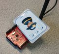
Sigfox Patrol Man : Sigfox Areku Board + Adafruit NFC Shield
Install the libraries Areku and Adafruit_PN532 (https://github.com/PM2M-2016-NFCSigfox/pm2m/tree/master/arduino/libraries) into the Arduino IDE.
Compile and load the sketch into the Areku board. (https://github.com/PM2M-2016-NFCSigfox/pm2m/blob/master/arduino/rondesNfc/rondesNfc.ino). The board type of the Areku board is "Uno".
#define DELAY_BETWEEN_MESSAGES 10000
#include <Akeru.h>

#include <Adafruit_PN532.h>
#include <SPI.h>
#include <SoftwareSerial.h>

#define PN532_CS 10 // La pin CS peut être connectée à la sortie D9 ou D10.
Adafruit_PN532 nfc(PN532_CS);
#define NFC_DEMO_DEBUG 1

void setup()
{
#ifdef NFC_DEMO_DEBUG
    Serial.begin(9600); // Vérification liaison série.
    // Init modem
    Akeru.begin();
    Serial.println("Bonjour!");
#endif
    nfc.begin(); // Démarrage puce PN532.

    uint32_t versiondata = nfc.getFirmwareVersion();

    if (!versiondata) {
#ifdef NFC_DEMO_DEBUG // Vérification PN532.
        Serial.print("Puce PN532 absente");
#endif
        while (1)
            ;
    }
#ifdef NFC_DEMO_DEBUG // Vérification paramétrage de la puce.
    Serial.print("Puce detectee, PN5");
    Serial.println((versiondata >> 24) & 0xFF, HEX);
    Serial.print("Firmware version: ");
    Serial.print((versiondata >> 16) & 0xFF, DEC);
    Serial.print('.');
    Serial.println((versiondata >> 8) & 0xFF, DEC);
    Serial.print("Supports ");
    Serial.println(versiondata & 0xFF, HEX);

#endif
    nfc.SAMConfig(); // Configuration de la carte pour lire des tags et cartes RFID.
}

void loop()
{

    // Attente de disponiblité (envoi d'un messages toutes les 11 minutes : 140 messages par jour max)
    while (!Akeru.isReady()) {
        Serial.println("Modem en mode attente.");
        delay(2500);
    }

    Serial.println("Modem OK");

    uint8_t uid[] = { 0, 0, 0, 0, 0, 0, 0 }; // Buffer pour stocker l'UID NFC
    uint8_t uidLength; // Taille de l'UID (4 or 7 octets)

    bool success = nfc.readPassiveTargetID(PN532_MIFARE_ISO14443A, uid, &uidLength);

    if (success) {
        Serial.print("UID Length: ");
        Serial.print(uidLength, DEC);
        Serial.println(" bytes");

        Serial.print("UID Value: ");

        for (uint8_t i = 0; i < uidLength; i++) {
            Serial.print(" 0x");
            Serial.print((byte)uid[i], HEX);
        }
        Serial.println("");

        // Envoyer les données
        if (Akeru.send(uid, uidLength)) {
            Serial.println("Send OK");
        }
        else {
            Serial.println("Send NOK");
        }
        Serial.print("Mode attente pendant ");
        Serial.print(DELAY_BETWEEN_MESSAGES);
        Serial.println("ms.");
        delay(DELAY_BETWEEN_MESSAGES);
    }
    else {
        Serial.println("Timed out waiting for a card");
    }
}
Check with the IDE Serial monitor the USB output of the board and put a NFC tag on the PCB antenna of the Adafruit NFC Shield.
Install and run the following Node.js script:
var PORT = 3000;
var PATH = '/sigfox';

//var BROKER_URL = "mqtt://localhost";
var BROKER_URL = "mqtt://test.mosquitto.org";
var TOPIC = "iotdays/sensors/sigfox";

var express = require('express');
var app = express();

var mqtt    = require('mqtt');
var client  = mqtt.connect(BROKER_URL);
var mqttConnected = false;

client.on('connect', function () {
  mqttConnected = true;
  console.log('Sigfox callback server : MQTT connected to ',BROKER_URL);
});

client.on('reconnect', function () {
  mqttConnected = true;
  console.log('Sigfox callback server : MQTT reconnected to ',BROKER_URL);
});

client.on('offline', function () {
  mqttConnected = false;
  console.log('Sigfox callback server : MQTT offline ');
});

client.on('close', function () {
  mqttConnected = false;
  console.log('Sigfox callback server : MQTT closed');
});

client.on('error', function (error) {
  mqttConnected = false;
  console.log('Sigfox callback server : MQTT Error ',error);
});


app.get(PATH, function (req, res) {
  console.log("Received ", JSON.stringify(req.query));
  if(mqttConnected) {
	client.publish(TOPIC, JSON.stringify(req.query));
	res.send('Callback received');
  } else {
  	res.status(500).send('Could not delivered callback');
  }
});

app.listen(PORT, function () {
  console.log('Sigfox callback server listening on port ', PORT);
});
npm init
npm install express --save
sudo npm install mqtt --save
cat package.json
node server.js
Configure the callback http://52.50.55.74:3000/sigfox?data={data}&id={device}&time={time}&snr={snr}&station={station}&avgSnr={avgSnr}&rssi={rssi}&lat={lat}&lng={lng}&seqNumber={seqNumber}&duplicate={duplicate} for the device into the Sigfox backend. (account is required)
Create a flow with a MQTT in node and a debug node.
Parse and display the values sent by the Sigfox backend : device, time, duplicate, snr, station, data, avgSnr, lat, lng, rssi, seqNumber
TBC
Remarks:
- The Sigfox modem can not send more than 144 messages due to the ETSI regulation.
- A Sigfox message contains up to 12 bytes (authenticated but not encrypted)
-
-
-

-
-
-


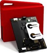
LoRa Patrol Man : STM32 Nucleo + NFC Shield

Arduino 101 BLE
TODO
-
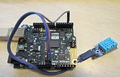
Genuino 101 + DHT11


Intel Quark D2000
TODO

SensorTag2 BLE
TODO
Follow the instructions here : https://github.com/uwefassnacht/ti-sensor-tag-demo
-
TI SensorTag2 Dev Kit


STEVAL-WESU1
-

TODO
K8055 Experiment IO Board
TODO
Johnny-Five
TODO
Pycom IoT Boards


File:Fipy.png FiPy (the full monty)TODO
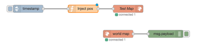
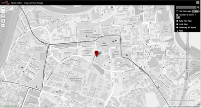
Plot geolocated devices on a Leaflet map
Install [1], a Node-RED node to provide a web page of a world map for plotting things on.
npm install node-red-contrib-web-worldmap
# restart Node-RED

[
    {
        "id": "3511f624.ade2aa",
        "type": "worldmap",
        "z": "ffdc6633.be43c8",
        "name": "Test Map",
        "lat": "45",
        "lon": "5",
        "zoom": "",
        "layer": "Esri Satellite",
        "cluster": "",
        "maxage": "",
        "usermenu": "show",
        "layers": "show",
        "panit": "true",
        "x": 1020,
        "y": 1780,
        "wires": []
    },
    {
        "id": "88d26ee5.8ca6b8",
        "type": "inject",
        "z": "ffdc6633.be43c8",
        "name": "",
        "topic": "",
        "payload": "",
        "payloadType": "date",
        "repeat": "",
        "crontab": "",
        "once": false,
        "x": 620,
        "y": 1780,
        "wires": [
            [
                "66ba0382.730ce4"
            ]
        ]
    },
    {
        "id": "66ba0382.730ce4",
        "type": "function",
        "z": "ffdc6633.be43c8",
        "name": "Inject pos",
        "func": "\n\n    msg.payload = {\n        name:\"My Lab\", \n        lat:45.19053, lon:5.76691\n        \n    };\n\n  return msg;",
        "outputs": 1,
        "noerr": 0,
        "x": 840,
        "y": 1780,
        "wires": [
            [
                "3511f624.ade2aa"
            ]
        ]
    },
    {
        "id": "c55666e6.f84c7",
        "type": "worldmap in",
        "z": "ffdc6633.be43c8",
        "name": "",
        "x": 980,
        "y": 1880,
        "wires": [
            [
                "ed61e82.61e0518"
            ]
        ]
    },
    {
        "id": "ed61e82.61e0518",
        "type": "debug",
        "z": "ffdc6633.be43c8",
        "name": "",
        "active": true,
        "console": "false",
        "complete": "payload",
        "x": 1170,
        "y": 1880,
        "wires": []
    }
]

Install Mosquitto
On MacOS X
brew install mosquitto
ln -sfv /usr/local/opt/mosquitto/*.plist ~/Library/LaunchAgents
launchctl load ~/Library/LaunchAgents/homebrew.mxcl.mosquitto.plist

echo Test connectivity
BROKER=localhost
mosquitto_sub -h $BROKER -t '$SYS/#'
On Debian
sudo apt-get install mosquitto
sudo service mosquitto status
sudo apt-get install mosquitto-clients
echo Test connectivity
BROKER=localhost
mosquitto_sub -h $BROKER -t '$SYS/#'
With Docker
docker pull eclipse-mosquitto
docker run -it -p 1883:1883 -p 9001:9001 -v mosquitto.conf:/mosquitto/config/mosquitto.conf -v /mosquitto/data -v /mosquitto/log eclipse-mosquitto
https://hub.docker.com/_/eclipse-mosquitto/


Test local Mosquitto broker
BROKER=localhost
mosquitto_sub -d -h $BROKER -t 'iotdays/sensors/#' &
mosquitto_pub -d -h $BROKER -t 'iotdays/sensors/gw0001' -m '{"device"="123456","temperature"=37.2}'
mosquitto_pub -d -h $BROKER -t 'iotdays/sensors/gw0001' -m '{"device"="345678","temperature"=23.2,"humidity"=50}'
mosquitto_pub -d -h $BROKER -t 'iotdays/sensors/gw0002' -m '{"device"="acr122u","nfc"="04ddf0f9232580"}'
sleep 1
pkill mosquitto_sub
Test public Mosquitto broker
BROKER=test.mosquitto.org
mosquitto_sub -d -h $BROKER -t 'iotdays/sensors/#' &
mosquitto_pub -d -h $BROKER -t 'iotdays/sensors/gw0001' -m '{"device"="123456","temperature"=37.2}'
mosquitto_pub -d -h $BROKER -t 'iotdays/sensors/gw0001' -m '{"device"="345678","temperature"=23.2,"humidity"=50}'
mosquitto_pub -d -h $BROKER -t 'iotdays/sensors/gw0002' -m '{"device"="acr122u","nfc"="04ddf0f9232580"}'
pkill mosquitto_sub
More:
- moquitto_pub manpage
- moquitto_sub manpage
- MQTT Spy : a graphical MQTT client in Java
- MQTT Dash for Android : a convenient MQTT dashboard for Android.
Using MQTT for collecting sensors data
In the flows defined above, add a node mqtt out with a new MQTT broker localhost:1883 and a topic iotdays/sensors/gwXXXX where gwXXXX is the name of the host.
Check the publishing with mosquitto_sub
BROKER=localhost
mosquitto_sub -d -h $BROKER -t 'iotdays/sensors/#' &
Create a new flow for subscribing messages from the Mosquitto MQTT broker.
Add a node debug for displaying the full message.
Add a node mqtt in with with a new MQTT broker localhost:1883 and a topic iotdays/sensors#
Connect the node mqtt in to the node debug.
Deploy the new flow.
Install InfluxDB
OS X (via Homebrew)
brew update
brew install influxdb
Ubuntu & Debian (64-bit)
wget http://dl.influxdata.com/influxdb/releases/influxdb_0.12.2-1_amd64.deb
sudo dpkg -i influxdb_0.12.2-1_amd64.deb
Ubuntu & Debian (ARM)
wget  --no-check-certificate http://dl.influxdata.com/influxdb/releases/influxdb_0.12.2-1_armhf.deb
sudo dpkg -i influxdb_0.12.2-1_armhf.deb
Docker
docker pull influxdb
docker run -p 8083:8083 -p 8086:8086 \
      -v influxdb:/var/lib/influxdb \
      influxdb
Populate InfluxDB from Node-RED
Launch the InfluxDB shell
influx
Enter the following InfluxDB statements
create database iotdb
show retention policies on iotdb
create retention policy three_hours_iot_training on iotdb duration 3h replication 1 default
show retention policies on iotdb
exit
In the Node-RED dashboard, create a new flow to collect sensors data from the MQTT server.
Install the Node-RED InfluxDB node.
Restart Node-RED.
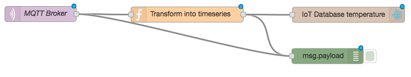
Add a node mqtt in "MQTT Broker" for subscribing to the MQTT server (broker is test.mosquitto.org or localhost topic is iotdays/sensors/#)
Add a node function "Tranform into time series" to format the JSON messages into time series messages.
Add a node influxdb out "IoT Database" with the InfluxDB server.
Connect the node "MQTT Broker" to node "Tranform into time series" and to the node "Tranform into time series" to node "IoT Database".
The flow looks like than:

Launch the InfluxDB shell
influx
Enter the following InfluxDB statements
use iotdb
show measurements
show series

select * from temperature
select * from humidity
select * from nfc
select * from ppm
select * from current
select * from sigfox
select * from lora
select * from weather
Extra for Arduino and Weather Shield
Add a node influxdb out
Add a node function with the following statements:
var result = {};
msg.payload.split(',').forEach(function(x){
    var arr = x.split('=');
    arr[1] && (result[arr[0]] = parseFloat(arr[1]));
});
msg.payload=result;
return msg;
Connect the 2 additionnal nodes like that:
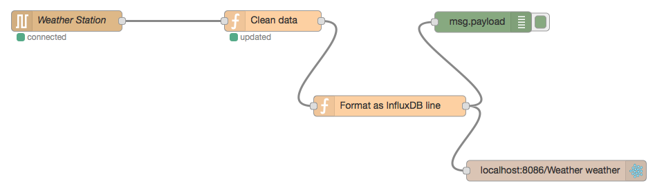

The flow is:
[{"id":"57400c2a.74f84c","type":"influxdb","z":"65e2c142.626cf8","hostname":"localhost","port":"8086","database":"iotdb","name":""},{"id":"40c61a94.428894","type":"serial-port","z":"65e2c142.626cf8","serialport":"/dev/tty.usbmodem1451","serialbaud":"9600","databits":"8","parity":"none","stopbits":"1","newline":"\\n","bin":"false","out":"char","addchar":false},{"id":"e0626709.612a1","type":"serial in","z":"65e2c142.626cf8","name":"Weather Station","serial":"40c61a94.428894","x":200.5,"y":486.5,"wires":[["576a5389.61c4e4"]]},{"id":"bf78bff1.63e8a","type":"debug","z":"65e2c142.626cf8","name":"","active":true,"console":"false","complete":"payload","x":802.5,"y":488,"wires":[]},{"id":"576a5389.61c4e4","type":"function","z":"65e2c142.626cf8","name":"Clean data","func":"var m=msg.payload;\nvar i=m.indexOf(\",\")+1;\nmsg.payload=m.substr(i,m.lastIndexOf(\",\")-i);\nsetTimeout(function() { node.status({}); }, 500)\nnode.status({fill:\"green\",shape:\"dot\",text:\"updated\"});\nreturn msg;","outputs":1,"noerr":0,"x":498.5,"y":486.5,"wires":[["86b78cd4.e2d548","bf78bff1.63e8a"]]},{"id":"86b78cd4.e2d548","type":"function","z":"65e2c142.626cf8","name":"Format as InfluxDB line","func":"var result = {};\nmsg.payload.split(',').forEach(function(x){\n var arr = x.split('=');\n arr[1] && (result[arr[0]] = parseFloat(arr[1]));\n});\nmsg.payload=result;\nreturn msg;","outputs":1,"noerr":0,"x":667.5,"y":610,"wires":[["1a959fff.cd4668","bf78bff1.63e8a"]]},{"id":"1a959fff.cd4668","type":"influxdb out","z":"65e2c142.626cf8","influxdb":"57400c2a.74f84c","name":"","measurement":"weather","x":908.5,"y":704,"wires":[]}]
Start the InfluxDB shell:
influx
Create the database with the foolowing statements:
create database iotdb
show retention policies on iotdb
create retention policy three_hours_iot_training on iotdb duration 3h replication 1 default
show retention policies on iotdb

use iotdb
show measurements
select * from weather
Install Chronograf
OS X (via Homebrew)
brew update
brew install homebrew/binary/chronograf
Ubuntu & Debian
wget https://s3.amazonaws.com/get.influxdb.org/chronograf/chronograf_0.12.0_amd64.deb
sudo dpkg -i chronograf_0.12.0_amd64.deb
Remark: Chronograf configuration directory is ~/chronograf.db
Docker
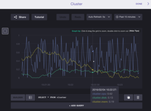
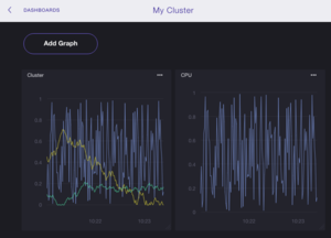
Visualize sensors data into the Chronograf dashboard
TODO
Browse https://localhost:10000/
Configure the InfluxDB datasource


Install Grafana (2.6)
On Debian
wget https://grafanarel.s3.amazonaws.com/builds/grafana_2.6.0_amd64.deb
sudo dpkg -i xzvf grafana_2.6.0_amd64.deb
sudo service grafana-server start
Docker
docker pull grafana/grafana
On Raspian Jessie
Visualize sensors data into the Grafana dashboard
Browse http://localhost:3000
Login with username:password  admin:admin
Change your admin password (optional)
Create a new dashboard
Add a data source (InfluxDB 0.9) iotdb (http://localhost:8086 direct root:root)
Save the data source
Enable dashboard edition.
Add a row.
Add a graph in the row.
Edit the graph.
Edit the query for the graph for the data source.
Save the dashboard.
Duplicate the graph and change the measurement in the query
Duplicate the graph and aggregate (mean) all measurements of the same type (temperature, humidity).
Set the timeline and the refresh time.
Save the dashboard.
Move and resize the graphs into the dashboard.
Save the dashboard.
See Grafana
The result should look like that
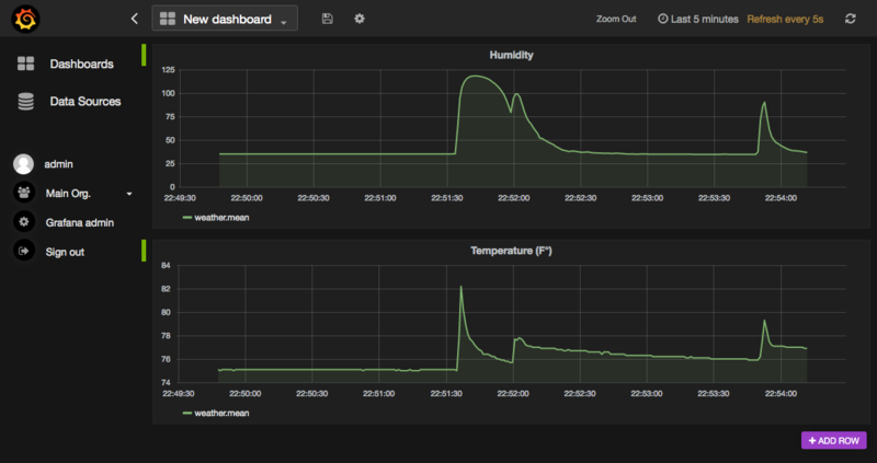

Install Apache Spark
See Spark
Process a realtime stream of sensors data with Apache Spark
TODO
import org.eclipse.paho.client.mqttv3._
import org.eclipse.paho.client.mqttv3.persist.MemoryPersistence

import org.apache.spark.storage.StorageLevel
import org.apache.spark.streaming.{Seconds, StreamingContext}
import org.apache.spark.streaming.mqtt._
import org.apache.spark.SparkConf

val brokerUrl = "tcp://localhost:1883"
val topic = "iotdays/sensors/#"
val ssc = new StreamingContext(sc, Seconds(60))
val sensordatas = MQTTUtils.createStream(ssc, brokerUrl, topic, StorageLevel.MEMORY_ONLY_SER_2)

TODO

ssc.start()
ssc.awaitTermination()
See
Annexes
Raspian Jessie commands
TODO
IBM IoT Watson
TODO
OVH IoT PaaS