Difference between revisions of "RobAIR2013-RICM4-Group-UML"
| (5 intermediate revisions by the same user not shown) | |||
| Line 1: | Line 1: | ||
| − | This page |
+ | This page regroups UML diagrams regarding the [[RobAIR2013 | RobAIR 2013]] project. |
=UML Diagrams= |
=UML Diagrams= |
||
| + | |||
| + | Unified Modeling Language (UML) is a standardized general-purpose modeling language that creates visual models of our system. UML is used to specify, visualize, modify, construct and document the artifacts of our system during its development. |
||
| + | |||
==UML global component diagram== |
==UML global component diagram== |
||
| + | |||
| ⚫ | |||
| + | <gallery> |
||
| ⚫ | |||
| + | Image:Architecture_04_02.jpg|ROS architecture |
||
| + | Image:ArchitectureROS.jpg|detailed ROS architecture |
||
| + | </gallery> |
||
| + | |||
| + | The UML global component diagram describes how our project is split up into components and shows the dependencies among these components. |
||
==UML sequence diagram== |
==UML sequence diagram== |
||
| Line 9: | Line 19: | ||
<gallery> |
<gallery> |
||
Image:sd_mov.jpg|sequence diagram regarding the deplacement scenario |
Image:sd_mov.jpg|sequence diagram regarding the deplacement scenario |
||
| − | Image: |
+ | Image:sd_info.jpg|sequence diagram regarding the info seeking scenario |
</gallery> |
</gallery> |
||
The UML sequence diagram shows how objects communicate with each other in terms of a sequence of messages. |
The UML sequence diagram shows how objects communicate with each other in terms of a sequence of messages. |
||
| − | |||
| − | |||
| − | [[Media:sd_mov.jpg|This UML diagram]] |
||
| − | [[Media:sd_info.jpg|This UML diagram]] |
||
==UML usecase diagram== |
==UML usecase diagram== |
||
| Line 25: | Line 31: | ||
</gallery> |
</gallery> |
||
| − | The usecase represents the list of interactions between the user and the robot.<br/> |
+ | The UML usecase represents the list of interactions between the user and the robot.<br/> |
=Appendices= |
=Appendices= |
||
Latest revision as of 22:09, 24 February 2013
This page regroups UML diagrams regarding the RobAIR 2013 project.
UML Diagrams
Unified Modeling Language (UML) is a standardized general-purpose modeling language that creates visual models of our system. UML is used to specify, visualize, modify, construct and document the artifacts of our system during its development.
UML global component diagram
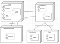
general component diagram
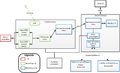
ROS architecture
detailed ROS architecture


The UML global component diagram describes how our project is split up into components and shows the dependencies among these components.
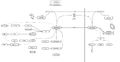
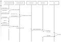
UML sequence diagram
sequence diagram regarding the deplacement scenario
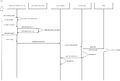
sequence diagram regarding the info seeking scenario


The UML sequence diagram shows how objects communicate with each other in terms of a sequence of messages.
UML usecase diagram
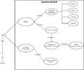
simple usecase (in French)
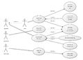
more complete usecase


The UML usecase represents the list of interactions between the user and the robot.
Appendices
Specification
The SRS (Software Requirements Specification) can be found here.
Group's pages
The global project's page can be found here.<br\> Three RICM4 groups are working on this project. Here are their wiki page:
Sources
- An exemple of JAVA node to communicate with ROS by Rémi Barraquand: http://github.com/PALGate/palgate-trial
- The RobAIR 2012 project by Thomas Calmant: http://github.com/tcalmant/robair